|
Obdstar X300 DP Plus is able to program the 2019 Nissan Sylphy B18 proximity key with a free pin code by OBD. Need to work with NISSAN-40 BCM Cable for the process. Read this guide to learn how to do it.
Check the video to learn:
Preparation
Remove the trim panel under the dashboard and locate the BCM module. Connect NISSAN-40 BCM Cable to BCM module. Connect to Key Master DP Plus via the main cable. 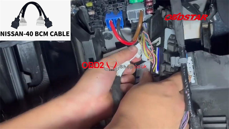
Operation
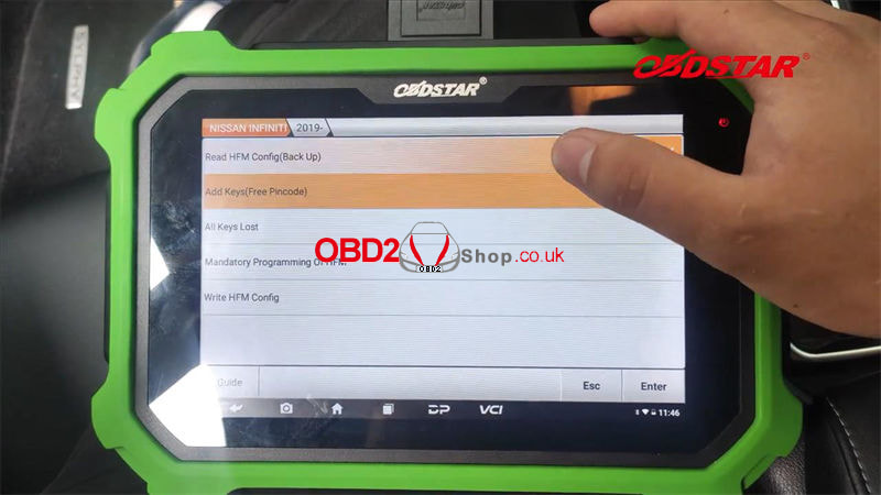
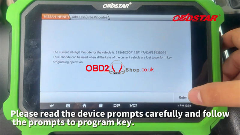
CAR IMMO >> NISSAN INFINITI >> Latest Version >> Manual Select System >> 28 Digital Pincode >> SYLPHY(B18)/SENTRA >> PROXIMITY >> 2019- >> Add Keys(Free Pincode) This function is available by connecting the server, please ensure the Internet connection is normal. Press "Enter". This function continues to need to unplug the gateway interface, and then use the dedicated Nissan/Renault 16+32 interface to connect to the unplugged gateway interface. Press "Enter" to continue. Note: 1. Executing this function will clear all the keys of the vehicle. The deleted keys must be re-programmed before they can be used normally; 2. Only 2 new keys can be programmed each time. If you need to program more than 3 keys. Please divide them into 2 operations; 3. There must be at least 1 key that can start the vehicle normally; 4. After the 4-button smart key programming is completed, if the transponder and the smart are not normal, please try to Write HEM Confin. Warning: 1. To ensure that the pincode is successfully read, please turn on the ignition switch; 2. The device must not be disconnected during the pin code reading process. Otherwise, the module will be damaged; 3. Please check the vehicle voltage, line connection, and other conditions to prevent the device from connecting abnormally in the middle. Press "Enter". Writing data, please wait for about 5 minutes... The current 28-digit pincode has been read out. This pin code can be used when all the keys of the current vehicle are lost to perform key programming operations. Press "Enter". 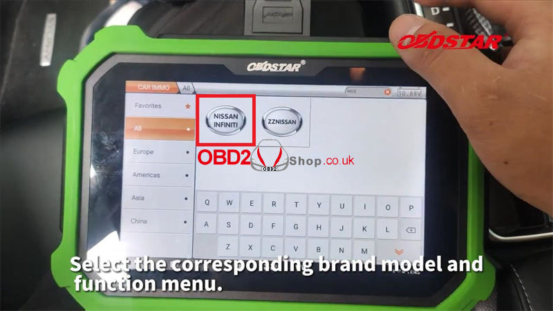
Turn on the double flash, and turn off the ignition switch.
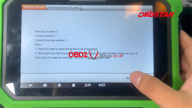
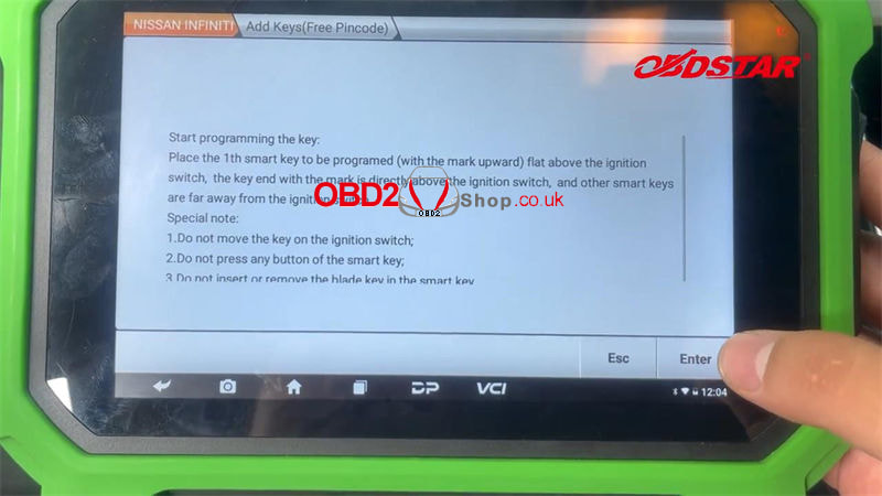
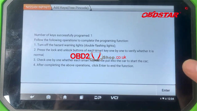
Switch the ignition on. 1. Long press the start button to turn off the ignition switch; 2. Turn on the hazard warning lights(double flashing lights); 3. The gear position is in P gear or neutral gear; 4. The steering column lock is in the unlocked state. Start to read the key ID: Place the 1st smart key to be programmed(with the mark upward) flat above the ignition switch, the key end with the mark is directly above the ignition switch, and other smart keys are far away from the ignition switch. Special note: 1. Do not move the key on the ignition switch; 2. Do not press any button of the smart key; 3. Do not insert or remove the blade key in the smart key. Press "Enter". New key number: 0 Old key number: 1 Current total key number: 1 Note: 1. Here you need to read all key IDs to be programmed; 2. New keys can only be programmed at most 2 keys, the total number of keys is up to 4; Press "Enter" to read the next key, "Esc" to the next step. Start programming the key: Place the 1st smart key to be programmed(with the mark upward) flat above the ignition switch, the key end with the mark is directly above the ignition switch, and other smart keys are far away from the ignition switch. Special note: 1. Do not move the key on the ignition switch; 2. Do not press any button of the smart key; 3. Do not insert or remove the blade key in the smart key. Press "Enter". The key is being programmed, please do not move the key... Program success. Number of keys successfully programmed: 1 Follow the following operations to complete the programming functions: 1. Turn off the hazard warning lights(double flashing lights); 2. Press the lock and unlock button of each smart key one by one to verify whether it is normal; 3. Check one by one whether each smart key can be put into the car to start the car; 4. After completing the above operation, press "Enter" to end the function. After all keys have been verified, please do not exit this function, press "Enter" to continue after completing the operation according to the following prompts: 1. Remove the dedicated Nissan/Renault 16+35 connector and restore the gateway module; 2. Connect the device to the vehicle OBDII connector and turn on the ignition switch. Program success. 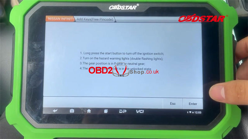
0 Comments
This is a tutorial on how to do mileage correction on Mercedes GLC 2017 using CGDI CG100X programmer. Note: This tutorial is created by CGDI Tech Support. 1. Check the car information (car type and car year). Got the car information from VIN-- GLC 2017. 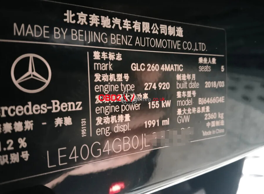 2. Check the current mileage. Better take a picture to record, we can see the current mileage is 125682km.  3. Remove the dashboard and check the chip number. The kilometers are stored in chip: R7F701414 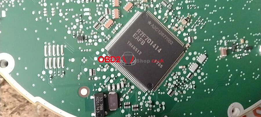  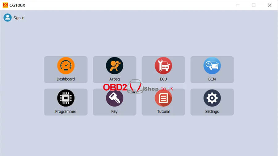 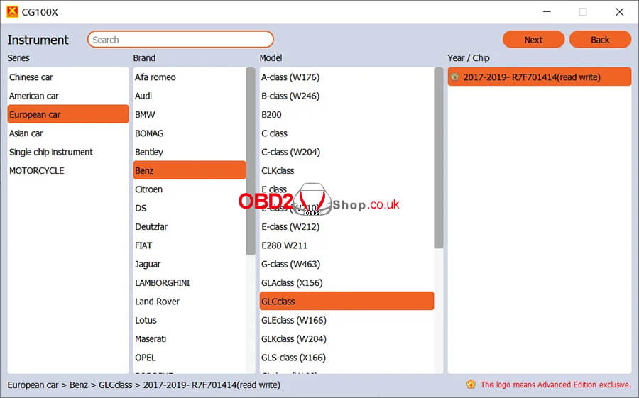 5. Connect the wires according to the diagram. 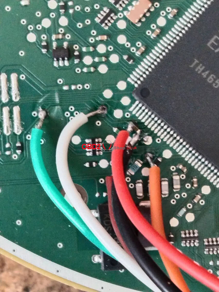 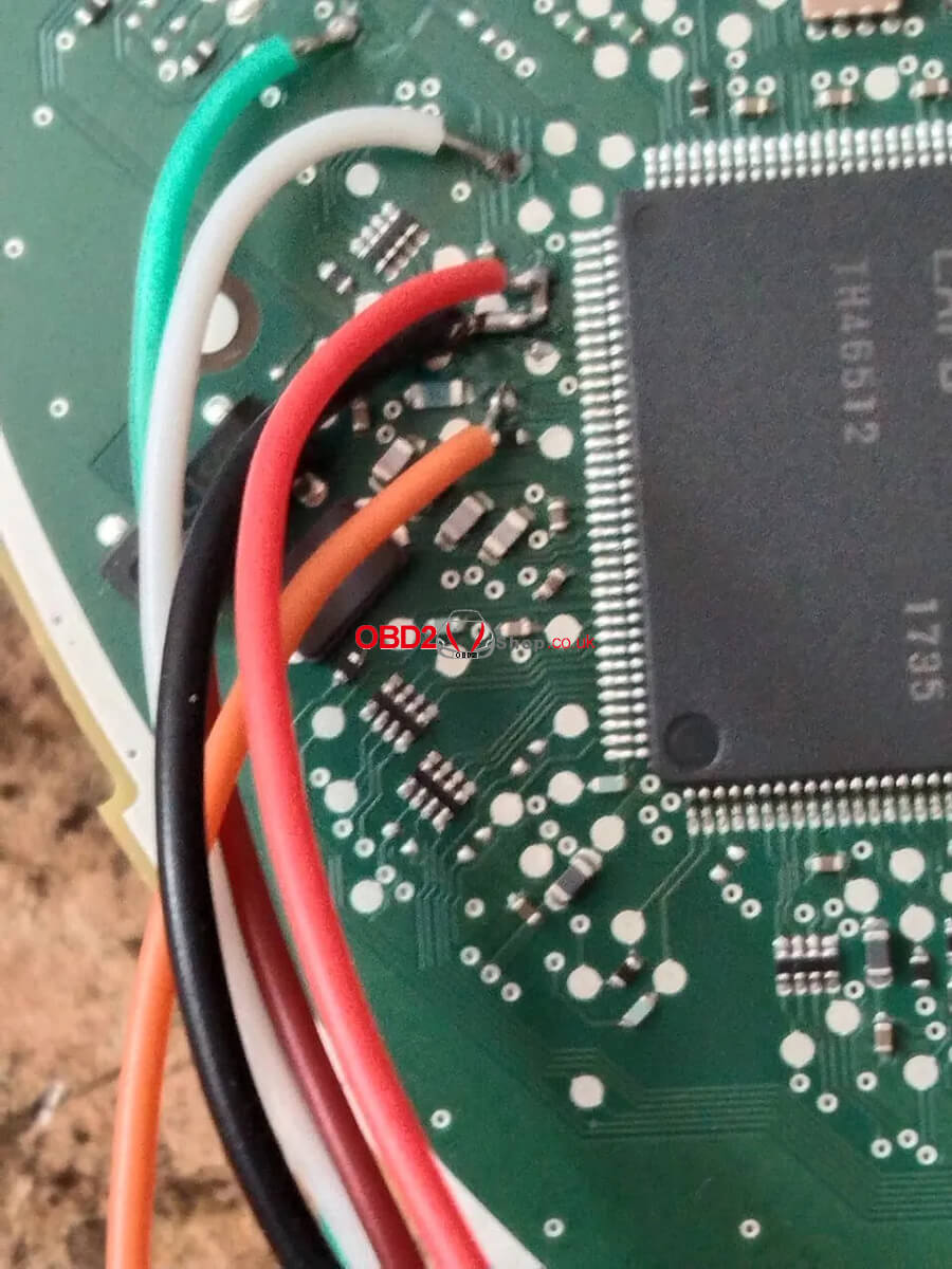 6. Read the data (check the km if the same as those displayed on the dashboard). 7. Write your target mileage of 73909 KM and wait for the software to change. 8. Put the dashboard back in the car and everything is ok. 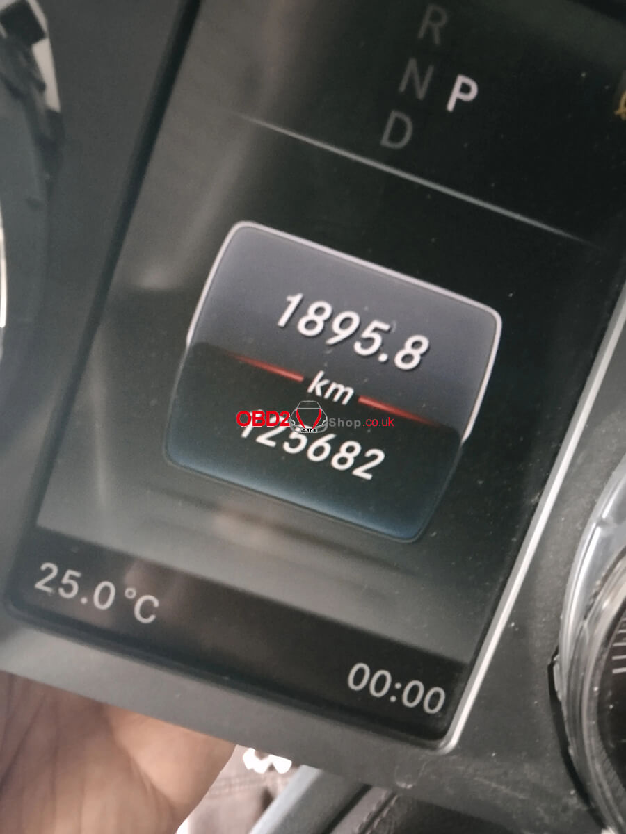 You may be interested in:
How to activate CGDI CG100X Programmer For more technical services, please follow https://www.obd2shop.co.uk/service/ Yanhua Module 30 & Module 30 Authorization has been newly released, which supports doing Volkswagen/ Audi DQ500(0BH Continental) gearbox mileage correction without soldering. Including Audi Q3(before 2016), and VW Multivan/ Tiguan vehicle models. Users who already have Module 19 or Module 25 can directly purchase the authorization. Other users can just purchase Module 30 to work with the Mini ACDP basic module. Module 30 Features 1. No soldering, no risk. It supports quickly identifying the vehicle transmission model by OBD without having to remove the computer. 2. It supports adjusting mileage by plugging the special interface board into the car, no need to remove the TCM. Module 30 Accessories 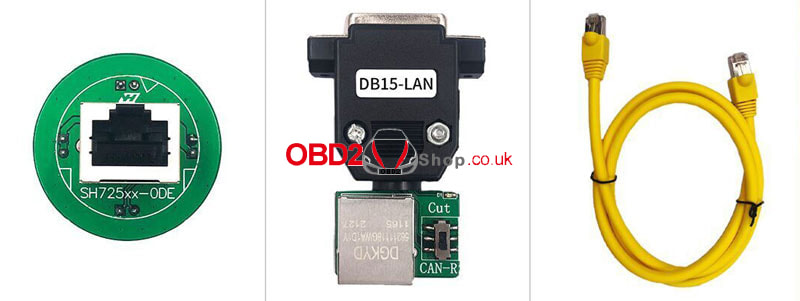 Module 30 APP Operation Steps Mini ACDP >> VW >> Gearbox mileage correction >> VW/ Audi >> DQ500(0BH CONTINENTAL) Here allows us to identify, mileage correction(auto mode/single-step mode), time correction(auto mode/single-step mode), read EEPROM, and write EEPROM. 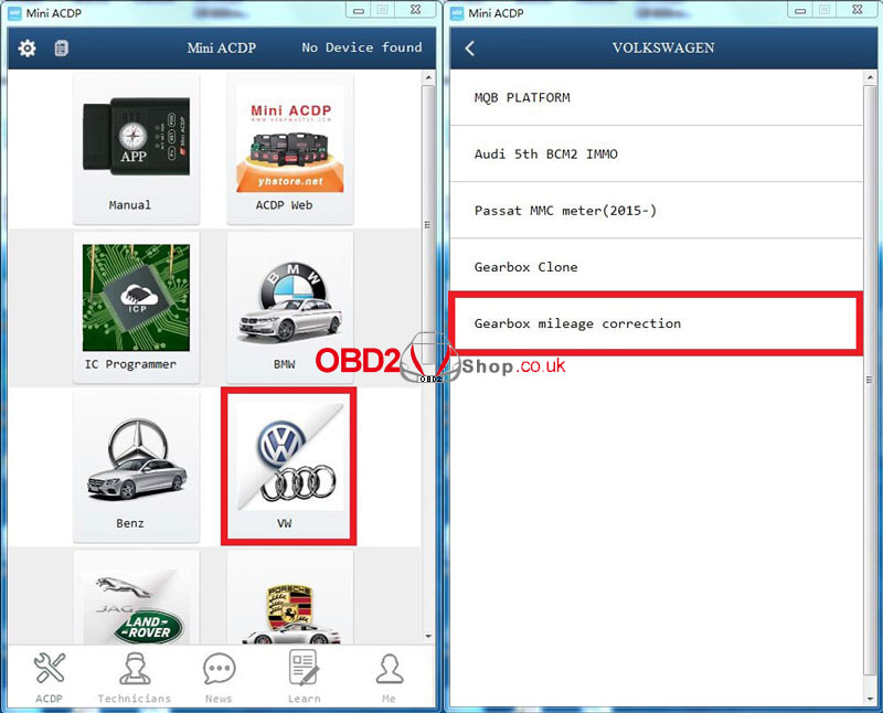 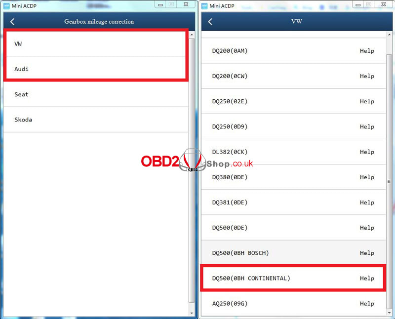 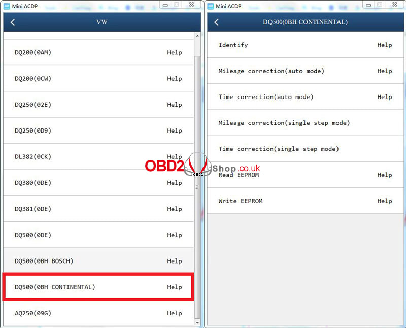 How to connect Module 30? 1. Prepare ACDP, DB15-LAN adapter, interface board, and gearbox. 2. Connect the interface board correctly to the gearbox interface. 3. Short the CAN resistor on the DB15-LAN adapter to the "CAN-R". 4. Connect ACDP, DB15-LAN adapter, interface board, and gearbox. 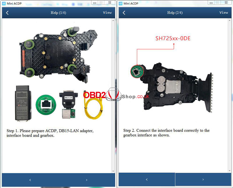 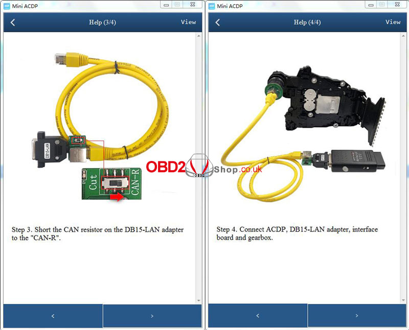 This post will guide you on how to activate CGDI CG100X Programmer. Step 1. Please download and install the newest software: https://mega.nz/folder/3CIXXDJC#jJ4CdJ9T-eEYhkBYi6Z65A 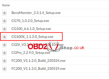 Step 2. Connect the CG100X USB cable and 12V 2A power adapter and open the software, the software will show you your instrument needs to be activated, click ok. 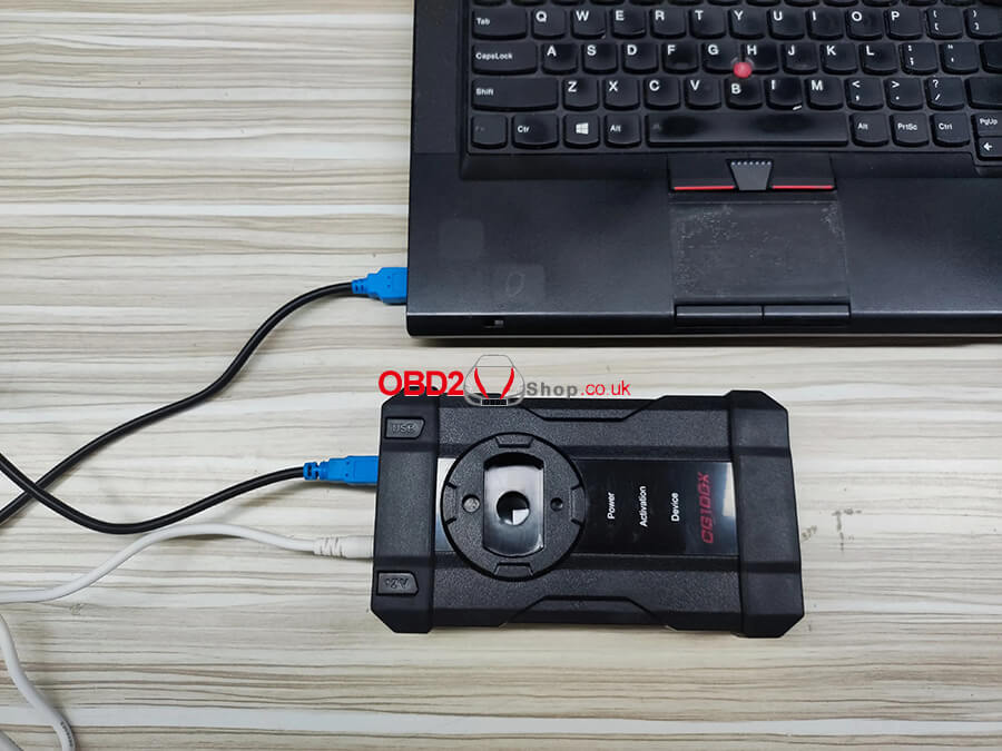 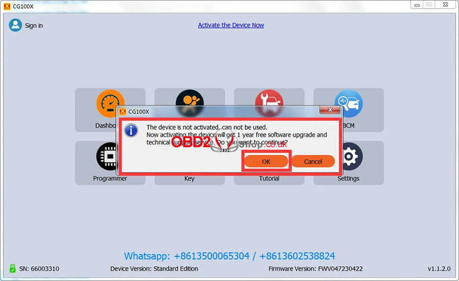 Step 3. Register an account and log in. If you already have an account from CGMB & CGDI & CGPRO & CG100, click OK and log in directly. 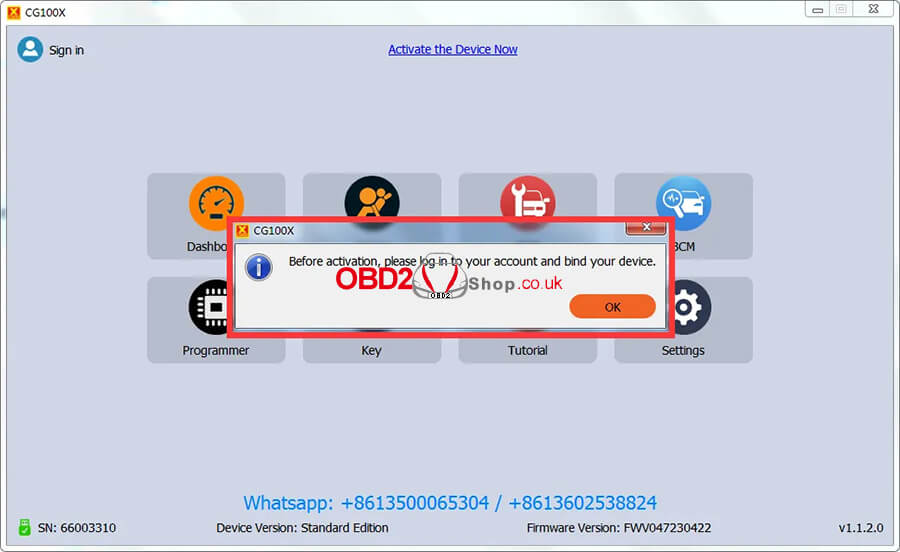 If you don't have an account, register for an account. Click ok and choose "No account? Create one!". (1) Better to type this information on a text file and save, copy, and paste it into the cg100X software when creating an account. (2) Better to use a simple username and password, it's easy to remember in the future. (For example, my account username is Lisa and my password is 12345678) (3) After entering all the information, click the "Submit" button. and an account has been created successfully. (4) Copy the username and password and log in. Then the tool will be activated successfully.  (5) If you cannot receive the code by phone number or email address, please change the server connection area one by one and try again. 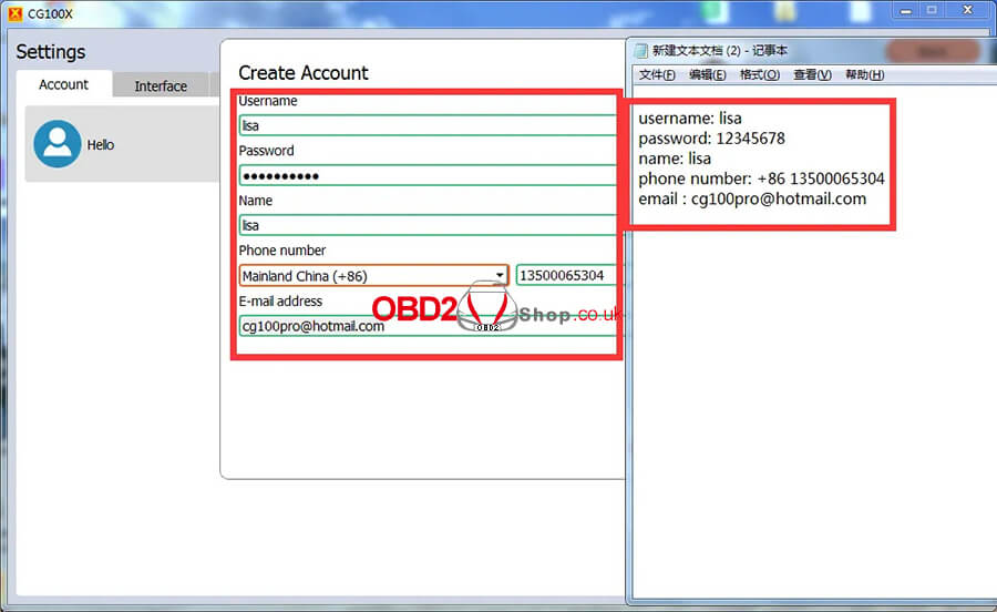 After you have successfully created an account, log in to the account. 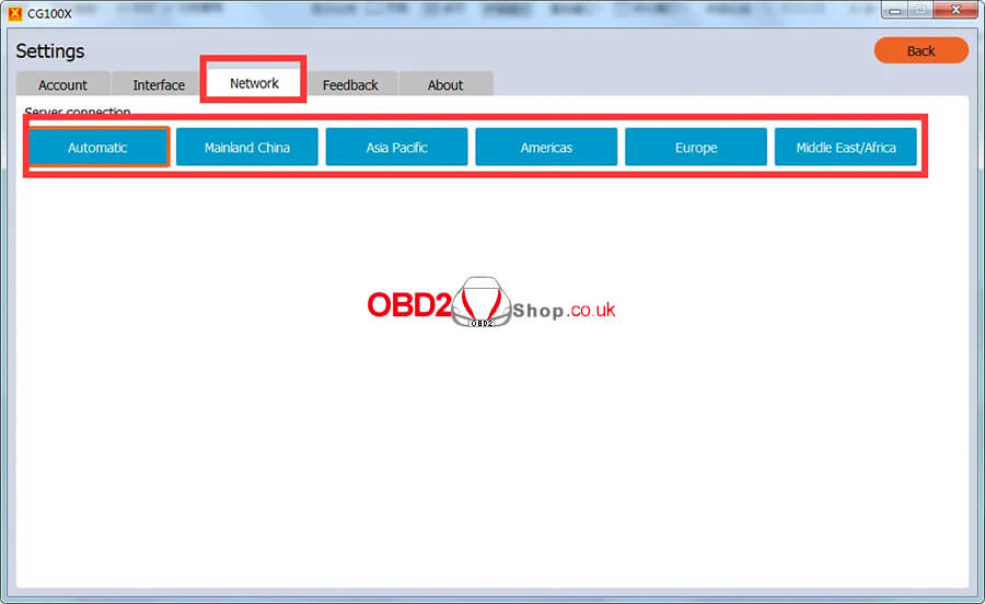 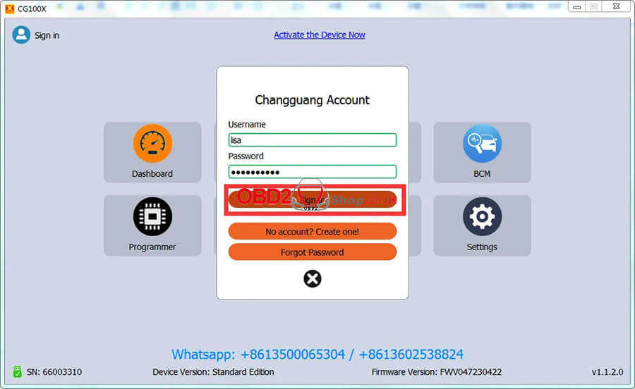 Step 4. After logging in, click on the "Activate the device now". 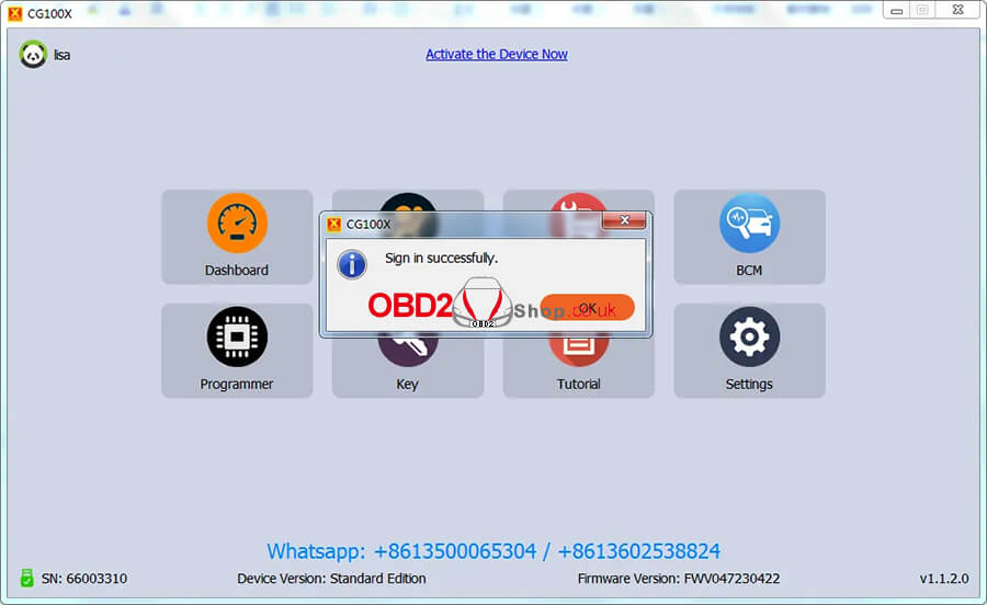 Then bind your device to your account, click "OK". 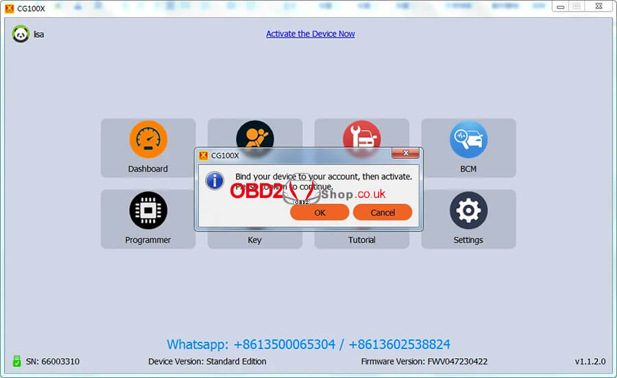 The tool has been activated successfully and you can see the subscription time 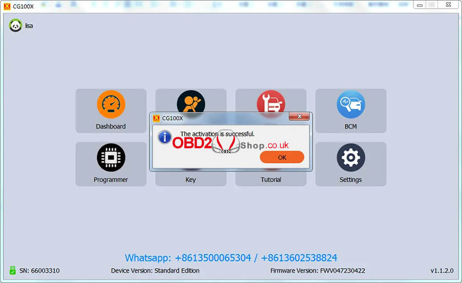 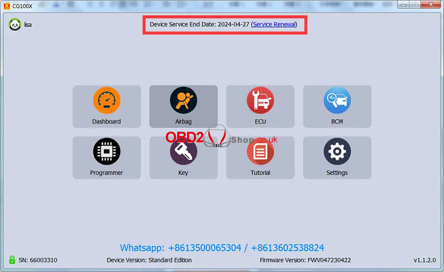 For more technical services, please follow https://www.obd2shop.co.uk/service/
This is a tutorial on how to use Yanhua Mini ACDP to read and write CAS ISN by ICP for DME replacement. Make sure you've purchased Module 1 & Module 27 before operation.
Here's replacing MSV80 as an example. The method also goes the same for BMW E/F chassis MSD80, MSD81, MSD85, MSD87, and MSV90 DME replacement. Full operation video:
Step1. Read The Donor DME ISN That Needs To Be Replaced
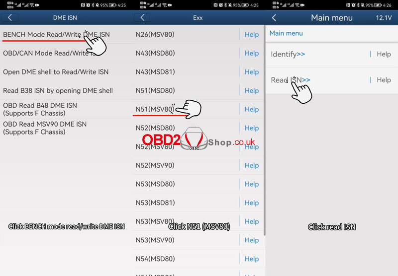
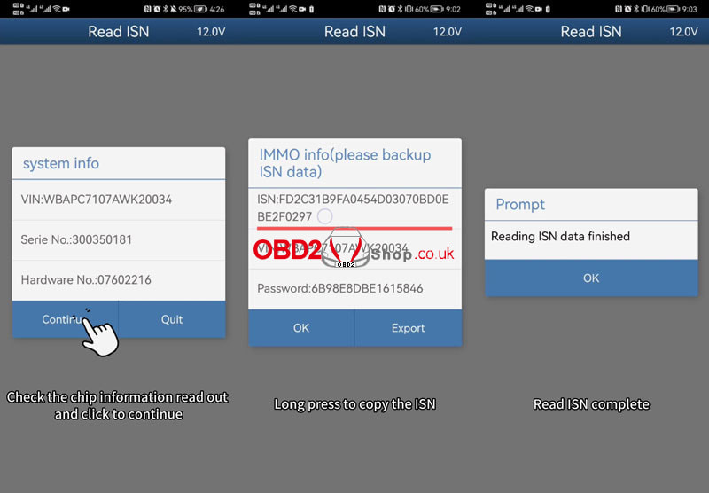
(NOT The Original DME) Installation: 1) Connect the MSV80 interface board to the DME, and connect the OBP+ICP adapter. 2) Shortcircuit the CAN resistor on the OBP+ICP adapter to the "CAN-R-JOIN" end. 3)Connect to the ACDP host and power on it. Operation: Mini ACDP >> Confirm Internet connection >> BMW >> DME ISN >> BENCH Mode Read/Write DME ISN >> SIEMENS/Continental DME >> Exx >> N51(MSV80) >> Read ISN Confirm that the connection between ACDP and DME is normal, click "Continue". Check the chip info readout, and click "Continue". Long press to copy the ISN(the ISN will be used later), and click "OK". Read ISN complete, and click "OK". 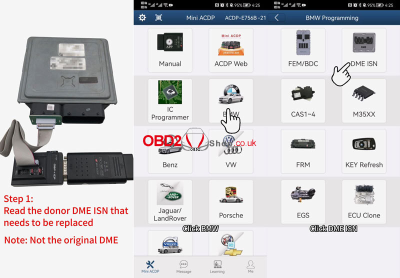
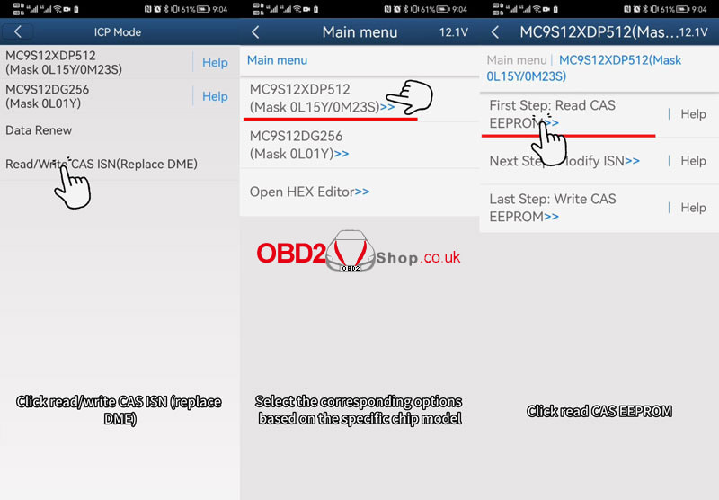
Step2. Read The Original CAS Data
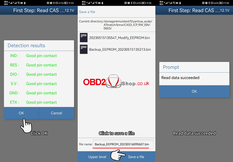
Stat Installing CAS3: 1) Find the location of the interface board positioning hole, and install the support studs. and BMW_CAS3 interface board. 2) Connect the OBP+ICP adapter to the BDM01 adapter. Connect BMW_CAS3 interface board. Return Back To BMW Option: CAS1~4 >> CAS3/CAS3+ >> ICP Mode >> Read/Write CAS ISN(Replace DME) >> MC9S12XDP512(Mask 0L15Y/0M23S) >> Read CAS EEPROM Confirm that ACDP is connected to the device normally, click "OK". Wait for pin detection to complete, and click "OK". Wait for the chip reading... Click "Save a file". Read data succeeded. 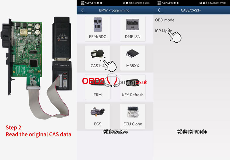
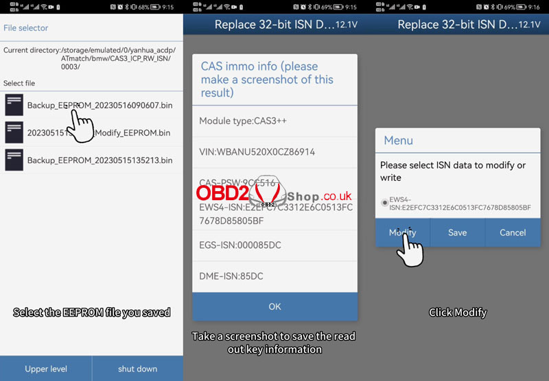
Step3. Modify CAS Data With Working Key
Installation: Unplug the OBP+ICP, connect the BAV KEY adapter to the ACDP host, and insert the working key. Operation: Modify ISN >> Replace 32-bit ISN DME >> OK >> Select the EERPOM file you saved Confirm that the connection between ACDP and BAV adapters is normal, click "OK". Take a screenshot to save the read-out key info, and click "OK". Modify >> Click ISN code and clear it >> Paste or enter the read donor DME ISN >> Modify Modify data finish. Save >> Save a file 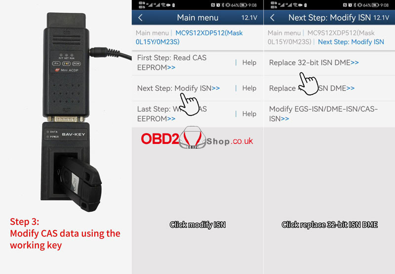
Step4. Write The Modified CAS Data
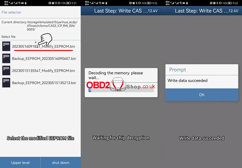
Installation: Unplug the BAV-KEY adapter, and connect the OBP+ICP. Operation: Go back to the previous step, and click "Write CAS EEPROM". Confirm that the connection between ACDP and the device is normal, click "OK". Wait for pin detection to complete, and click "OK". Please select EEPROM data. Waiting for chip decryption... Write data succeeded. DME replacement completed. 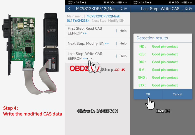
This is a guide for you to use Yanhua Digimaster 3 + solderless adapter for mileage adjustment. Including installation and operation step by step. How to install Yanhua D3 & solderless adapter? 1. Connect Digimaster 3 and Yuanhua solderless adapter via a power cable.  2. Connect the chip and Yuanhua solderless adapter via chip clip or Puncture socket. The red line needs to match Pin1 of the chip. 3. Select the corresponding chip model through "CHOOSE" on the adapter: My dashboard computer here is a 2009 VW Bora, chip no. 24C32. So I gonna choose 24XXX, then press test, and start pin detection. *If the pin detection fails, please adjust the chip clip and press the test again. 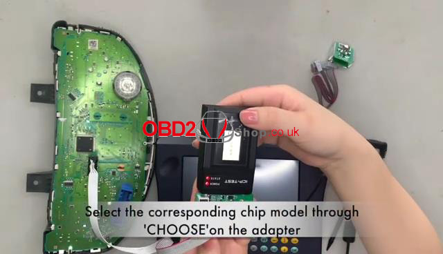 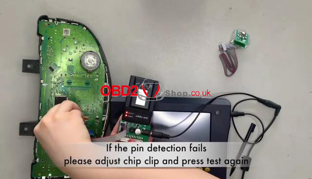 4. When pass the pin detection, connect the adapter and Digimaster 3 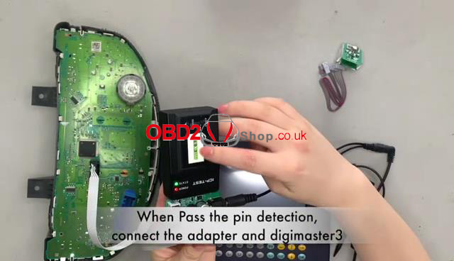 How to use Yanhua D3 for mileage correction? Meter system >> Europe >> Volkswagen >> Bora >> 18G920826 >> 2009 and next Check the original mileage, and press "YES". Save the original data. 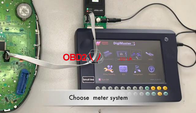 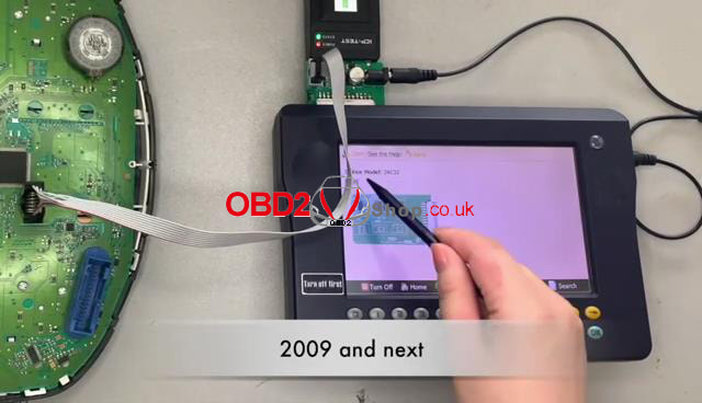 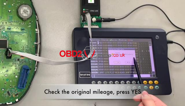 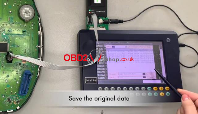 Now we can program new mileage. Enter the new mileage value, then choose "OK". Mileage adjustment is successful. Complete. 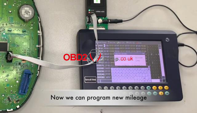 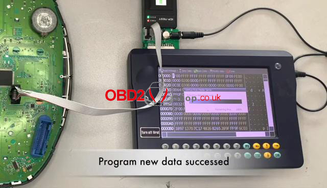
This article is about Autel MaxiSYS MS908S PRO II report saving and cloud share function display.
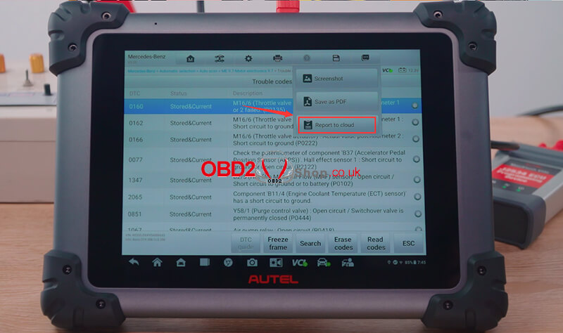
Here comes the steps: Click "Diagnostics", select the SAVE logo in the upper right corner of the screen, and click "Report to Cloud". 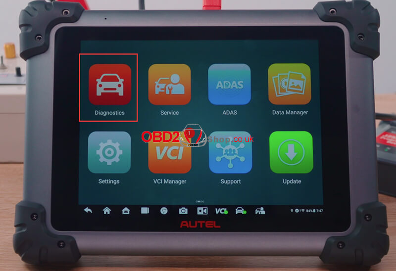
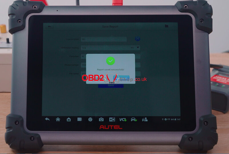
Fill in the corresponding information and click "Save".
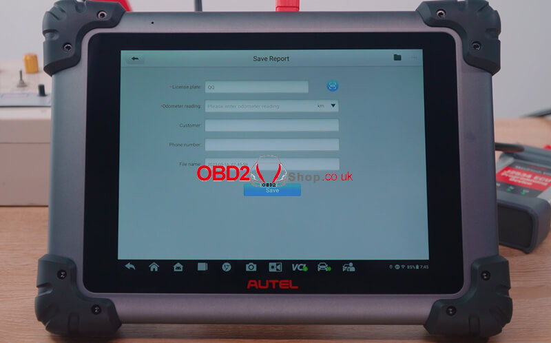
Report saved successfully!
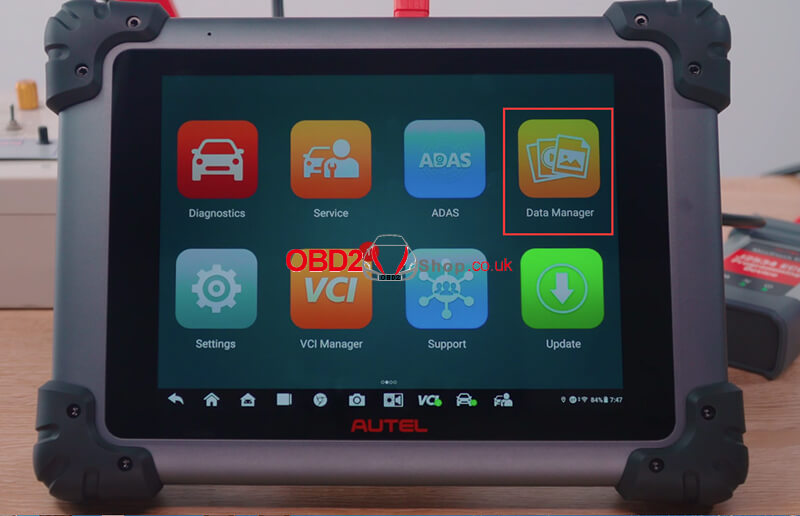
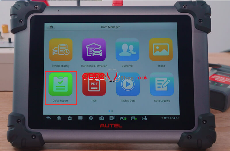
Go back to the previous interface, and click "Data Manager" >> "Cloud Report".
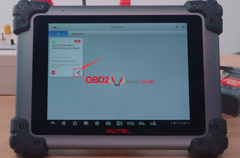
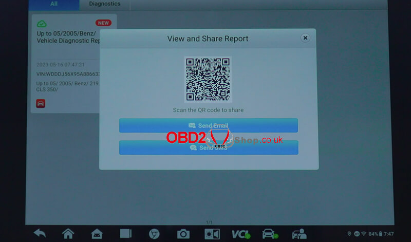
Click the share icon to share the report.
As the picture shows, there are three ways to share, here we choose "Send Email".
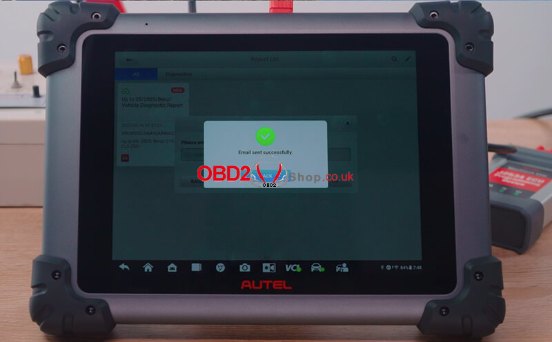
Email sent successfully!
Video Guides:
OBDSTAR D800 is a new generation diagnostic tool for marine, working for jet skis, outboard, inboard, and generators. Based on the Samsung Exynos processor and the new Android 5.1.1 system, D800 is fast and smooth to be a good helper for marine maintenance engineers.
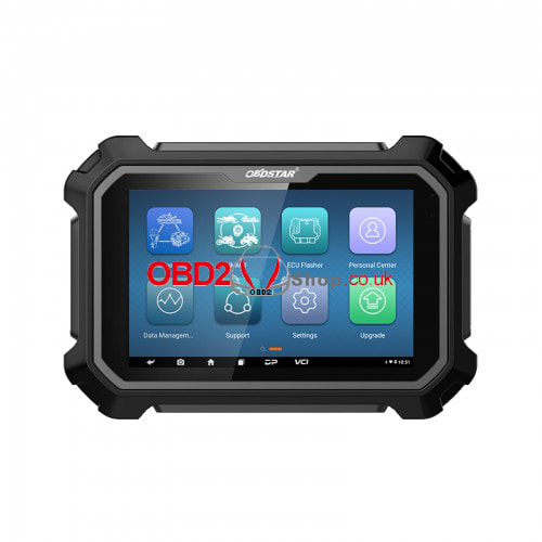
Software
There are 2 software configurations for selection: D800A & D800B
Features
1. Provides complete diagnosis including checking ECU info, reading & clearing codes, data flow, freeze frames, actions test, setting, coding, etc. 2. Record and playback real-time flow, which allows users to accurately locate sensor and component faults. 3. Can work with OBDSTAR APP to get more functions than the D800 device itself. Such as diag socket location, flash code query, technical bulletin, service lamp reset, basic parameters, etc. 4. OBDSTAR technical staff one-click remote assistance. 5. One-click software upgrade via Wi-Fi. 6. Supports advanced functions such as Auto Scan, Active Trim Configuration, Active Trim GPS Configuration, Auxiliary Joystick Configuration, BCM Simulator, Compass Configuration, Device Initialization, Drive Alignment, Helm Setup, Instance Setting, Maintenance Setting, Merc TDS Reset, Remote Control Reset, Set Engine Location, Set Tach Link, Set Tilt Limit, SMUX Congfiguration, Steering Wheel Centering, System Calibration, Torque Adjustment, Trackpad Configuration, Vessel Personality, etc. 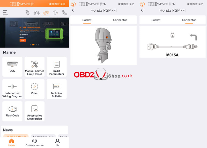
Supported Brands
EVINRUDE, HIDEA, HONDA, JOHNSON, KAWASAKI, MARINER, MERCURY/MERCURY RACING, PARSUN, SEA-DOO(BRP), SELVA MARINE, SEVEN MARINE, SUZUKI, TOHATSU, YAMAHA... 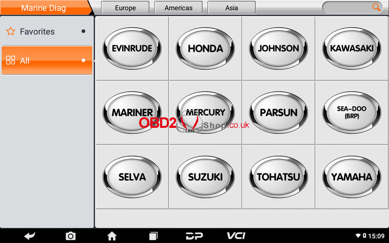
Optional Brands
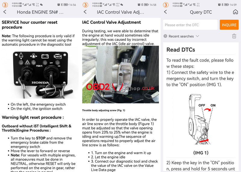
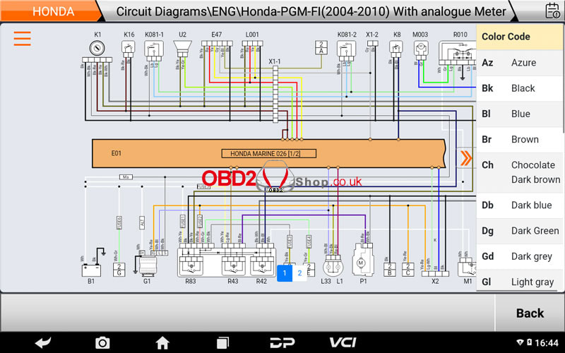
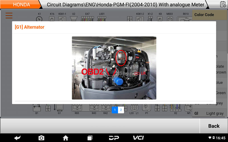
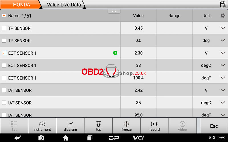
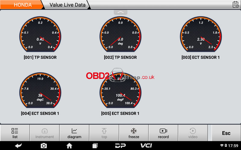
CATERPILLAR, CFMOTO, CRUSADER ENGINES, CUMMINS MARINE, CUMMINS MERCRUISER DIESEL, DAEDONG, DAF MARINE, FNM MARINE, FORD MARINE, FPT (Fiat Powertrain Technologies), HYUNDAI SEASALL, ILMOR, INDMAR, JOHN DEERE MARINE, KODIAK MARINE, KOHLER POWER SYSTEMS, LOMBARDINI MARINE, MALIBU, MAN MARINE, MARINE POWER, MTU, PANTHER AIRBOATS, PCM Marine Engines, PERKINS, SCANIA MARINE, SISU, STEYR MOTORS, TOYOTA MARINE, VM MOTORI, VOLKSWAGEN MARINE, VOLVO PENTA, YANMAR... OBDSTAR D800 Diagnose Honda Outboards Connect D800 to Honda outboard via M001B cable & M015A Honda cable. Marine Diag >> HONDA >> Latest version >> Diagnosis >> Serial A >> AquaTrax F-12(ARX1200N3) >> ENG >> Honda PGM-FI(2004-) For the US/CANADIAN >> DTC Here we can read DTC, read the data stream, and do the active tests, and special functions. Operation video:
OBDSTAR D800 Diagnose YAMAHA Outboards
Connect D800 to YAMAHA outboard via M001B cable & M061 YAMAHA cable. Marine Diag >> YAMAHA >> Latest version >> Diagnosis >> ENG >> OK Here we can check ECU info, read DTC, read data stream, and do active tests. Operation video:
OBDSTAR D800 Diagnose Suzuki Outboards
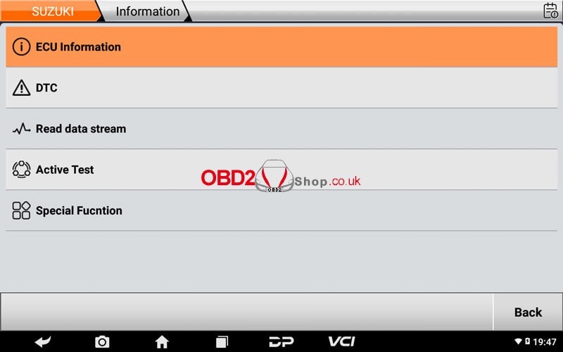
Connect D800 to Suzuki outboard via M001B cable & M062 Suzuki cable. Marine Diag >> SUZUKI >> Latest version >> Diagnosis >> Auto identify(CODE) Here we can check ECU info, read DTC, read data stream, do active tests, and special functions. Operation video:
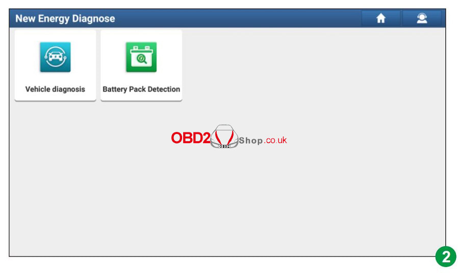
Launch X431 is now able to diagnose electric vehicles by purchasing X431 EV Diagnostic Upgrade Kit. Currently is only compatible with X431 PAD VII & X431 PAD V. Check this article to learn the supported car list.
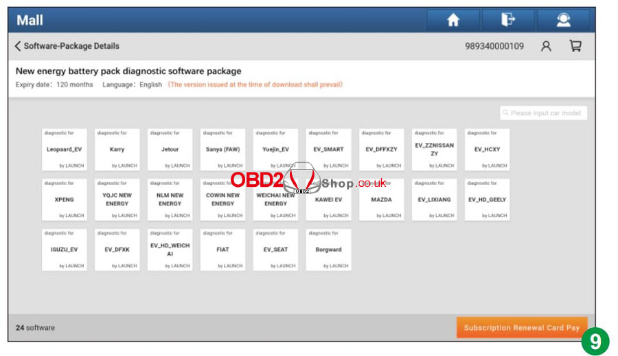
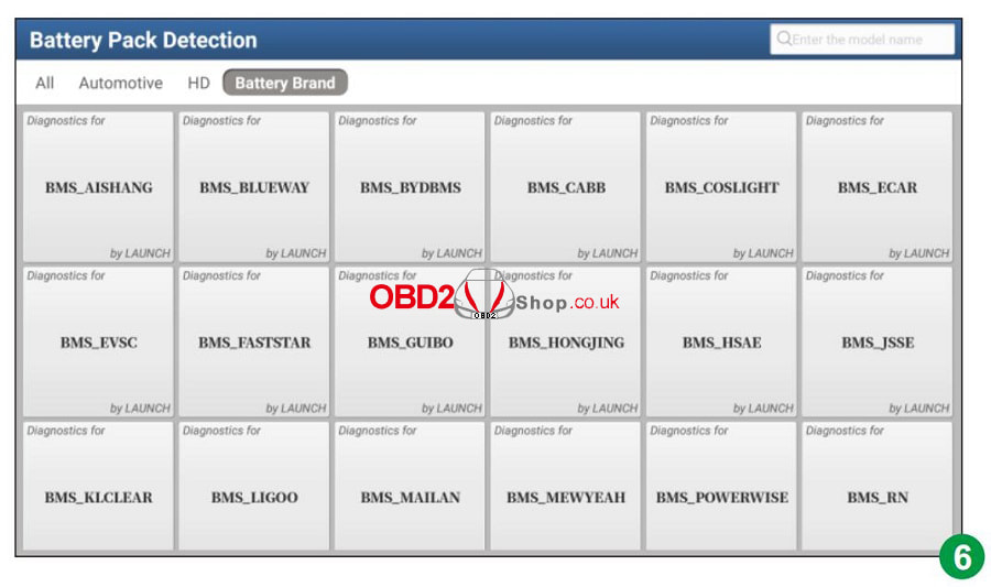
X431 EV Diagnostic Software Support List
This post will guide you on how to use Yanhua Mini ACDP and ACDP Module 8 to repair the BMW FRM module.
Attention: Before purchasing Module 8, make sure you already have ACDP Module 1 Check the required accessories: BMW FRM Module ACDP Main unit OBD+ICP Adapter 20 Pin Cable FRM interface board Screws BDM01 adapter (from module 1) 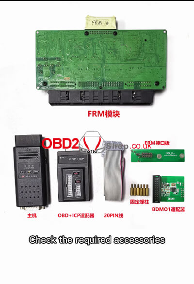
Install the support studs
Install the FRM interface board Note that the test pins of the FRM interface board should be aligned with four test points 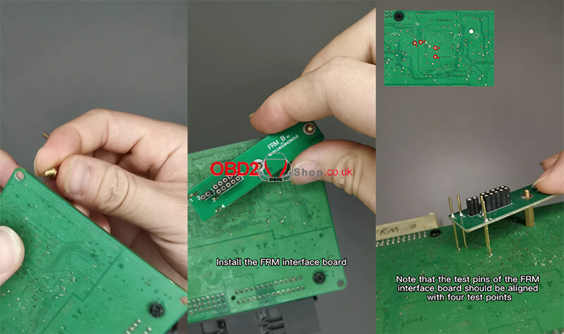
Lock two screws
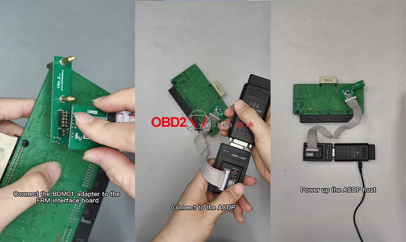
Connect the BDM01 adapter to the OBP+ICP adapter Connect the BDM01 adapter to the FRM interface board Connect to the ACDP Power up the ACDP host 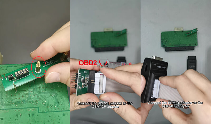
Open the ACDP software
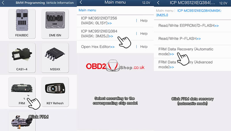
Confirm in the upper right corner that ACDP connected Click "BMW" >> "FRM" Select according to the corresponding chip model, here we choose"ICP MC9S12XEQ384 (MASK:3M25J)" Click FRM data recovery (automatic mode) 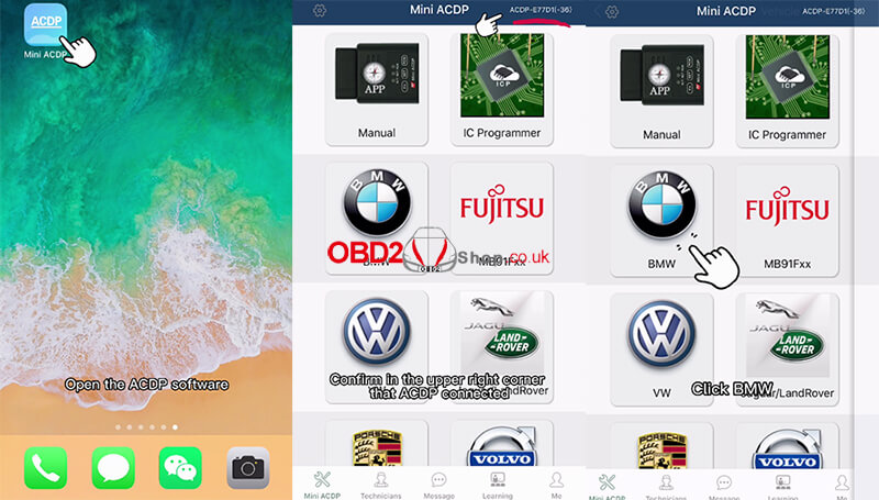
Confirm that the device and adapter are connected properly
Waiting for pin detection to pass Click Confirm 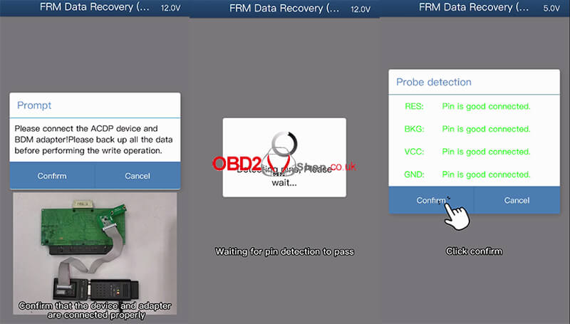
Reading chip data
Check the chip information readout If 4K EEPROM data is read The FRM module data is not damaged Please operate with caution If 32K Dflash data is read The FRM module data is corrupt Click Confirm to continue 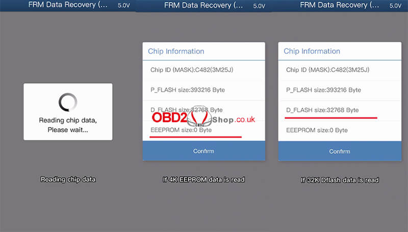
Pay attention to the path to save the file, which includes the date and time
Check the frame number and other information If the parsed car information is incorrect Click Cancel to the exit automatic repair If the information such as the car correct. click confirm Repairing chip data Repair completed! 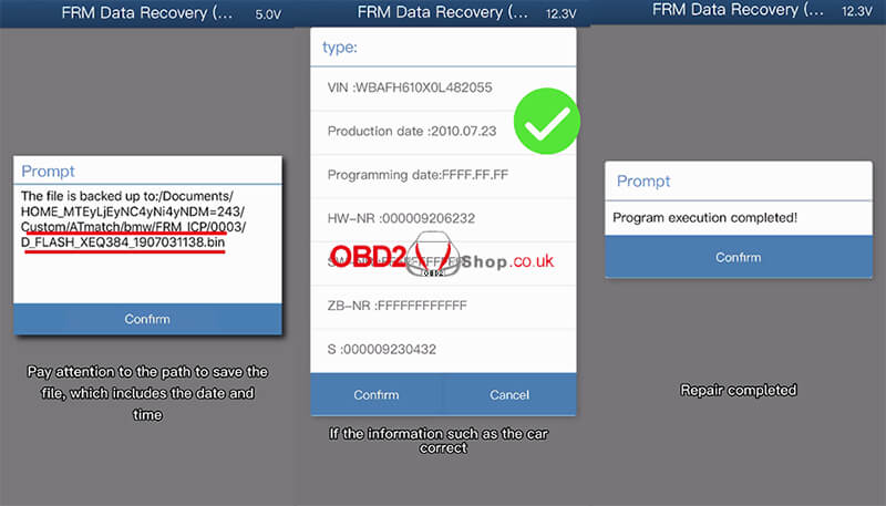
Check the video to learn more details:
|
|||||||||||||||||||||||||||||||||||||||||||||||||||||||||||||||||||||||||||||||||||||||||||||||||||||||||||||||||||||||||||||||||||||||||||||||||||||||||||||||||||||||||||||||||||||||||||||||||||||||||||||||||||||||||||||||||||||||||||||||||||||||||||||||||||||||||||||||||||||||||||||||||||||||||||||||||||||||||||||||||||||||||||||||||
