|
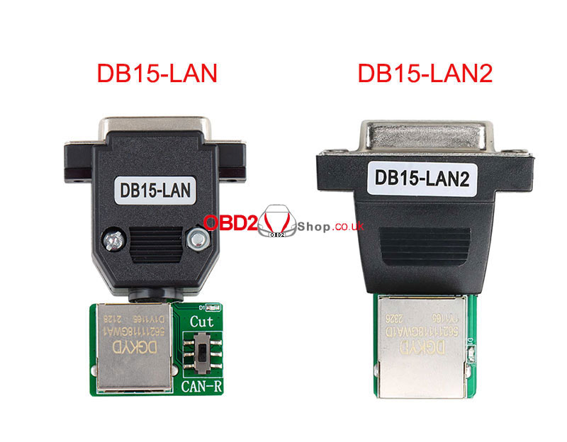
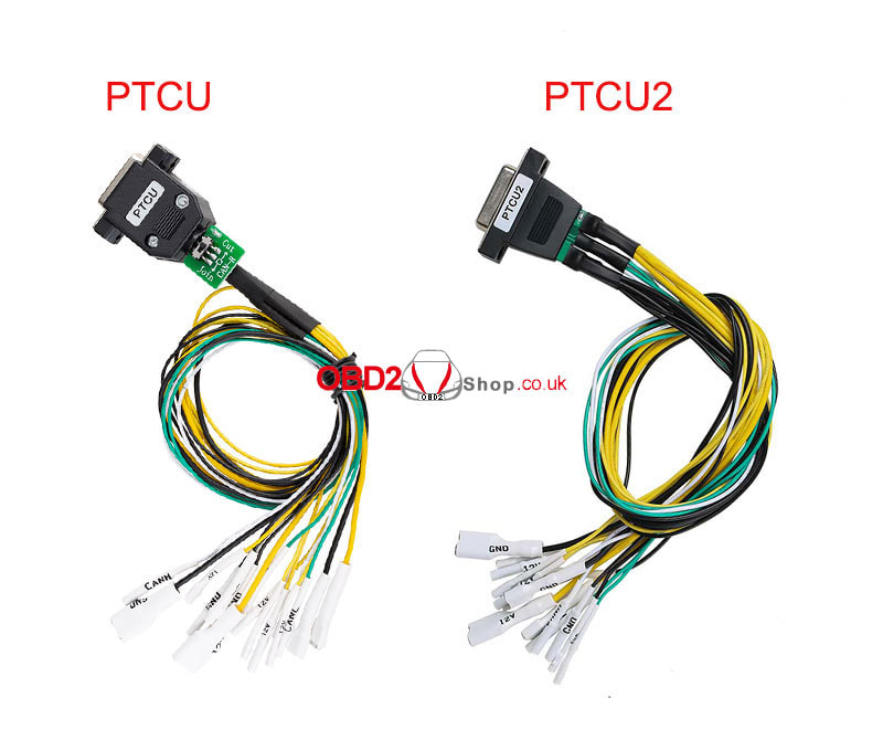
This post shows how to modify the DB15-LAN and PTCU adapters in ACDP-1 Module 19 to fit ACDP-2.
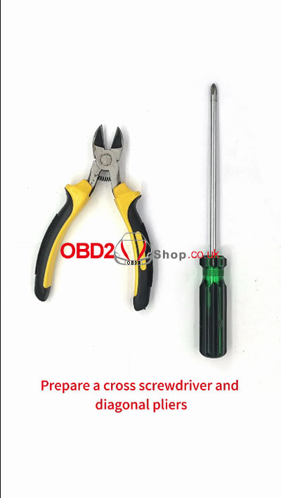
Prepare a cross screwdriver and diagonal pliers.
Use a phillips screwdriver to remove the screw on DB15-LAN and PTCU.
Disassemble the casing. 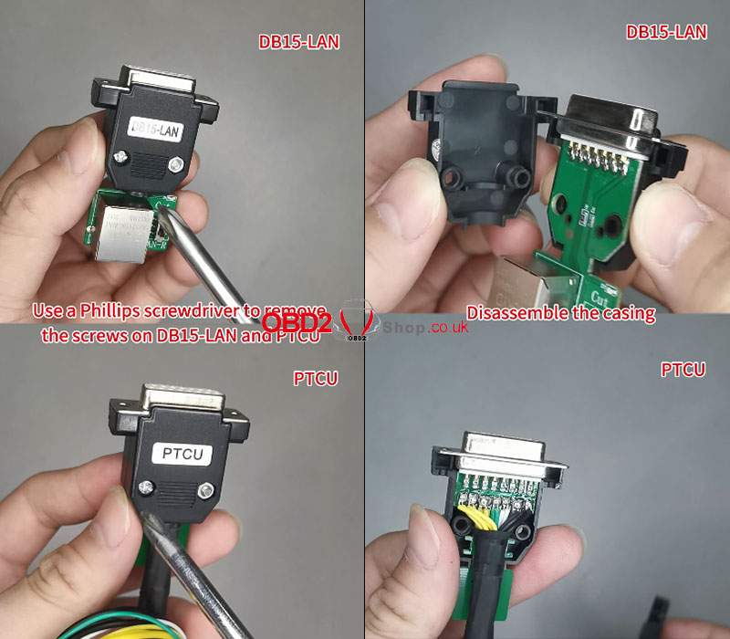
Use diagonal pliers to cut the protruding parts of the front ends of the two shells flat.
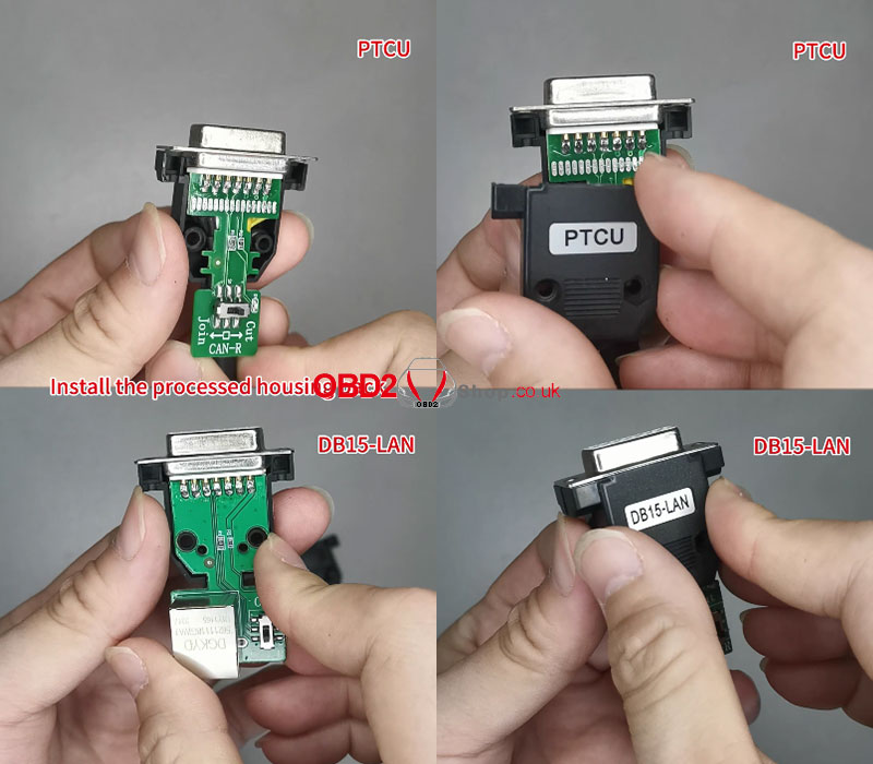
Install the processed housing back. 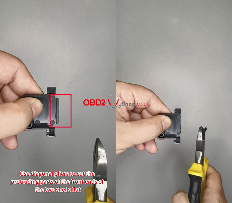
Tighten the screws.
DB15-LAN and PTCU shell processing completed. 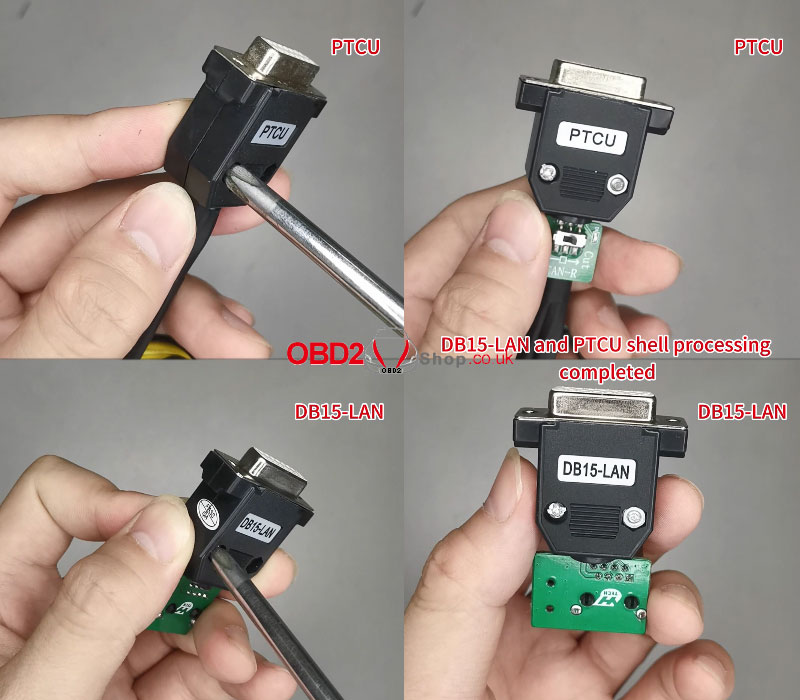
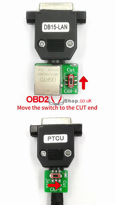
Move the switch to the CUT end.
Video guides:
0 Comments
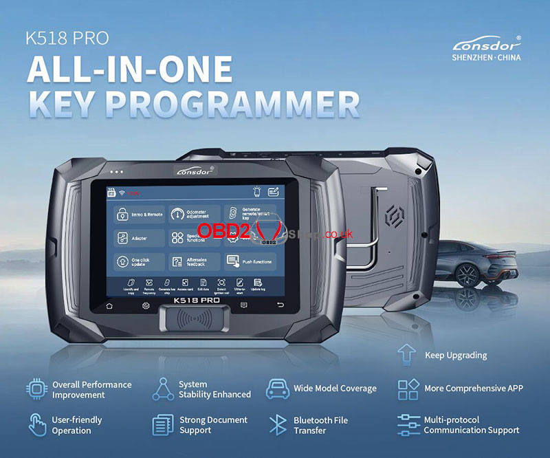
Lonsdor K518 PRO is an all-in-one programming device that follows the great success of Lonsdor K518. With Lonsdor's strong technical capabilities, K518 PRO has received updates. It's featured with built-in LKE, Bluetooth, file management, anti-theft deactivation, access card copy, data write initialization, EEPROM data mileage restoration, CAN-FD protocol, DOIP protocol. K518 PRO Function Interface 1. Immobilizer supports the latest CAN-FD & DOIP protocols. 2. Add EEPROM odometer adjustment. 3. Generate remote/smart 4. Read & write MCU/EEPROM via adapter. 5. Built-in LKE function Unlock 8A/4D original key(from car manufacturer) LT-8A/4D key settings/AKL/copy. 6. Add Bluetooth/Ethernet settings, language switch, and file manager. 7. One-click update. 8. Aftersales feedback. 9. Push function. K518 PRO Specifications 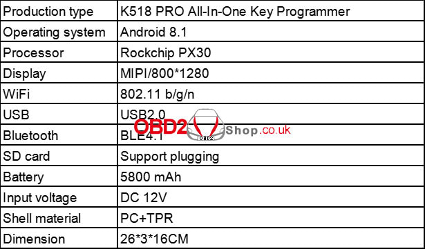 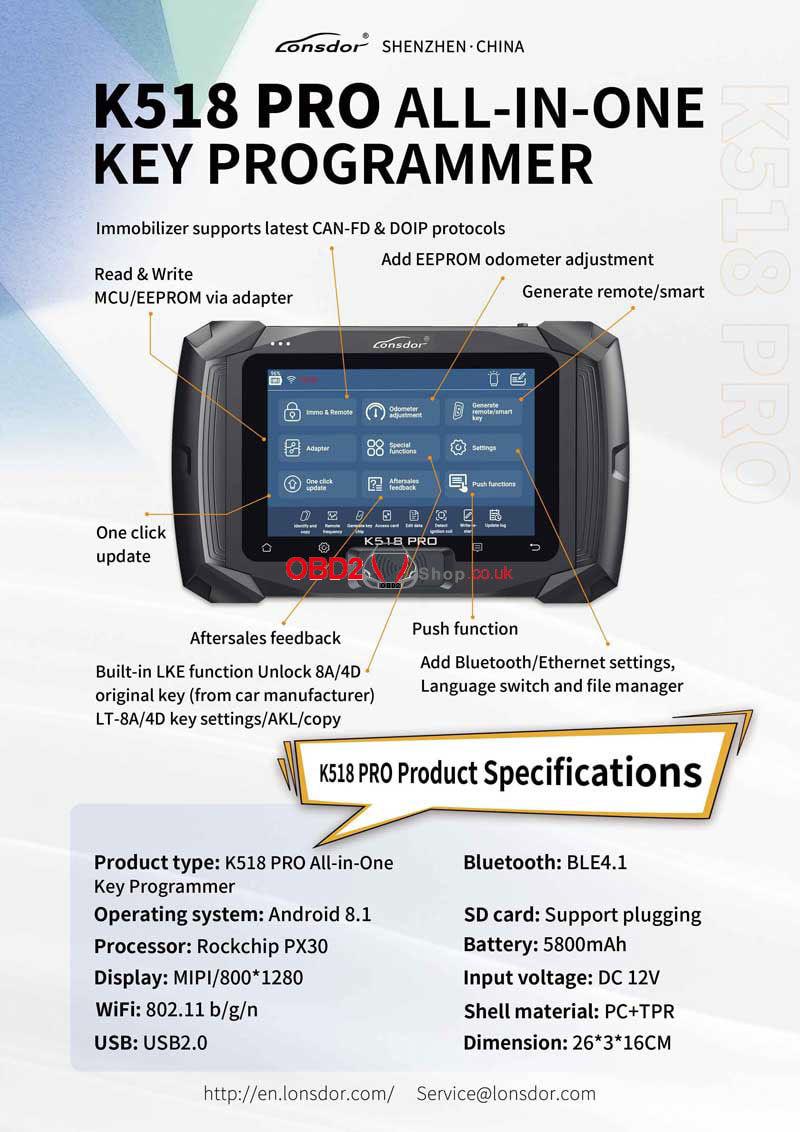 K518 PRO Vehicle Compatibility List Support Volvo S40/S60/S80/S90/V40/V60/V70/V90/C30/C70/XC40/XC60/XC70/XC90 all series IMMO. Support the latest Toyota/Lexus chip type 8A/4A smart key programmed with a free pin code. Support 2015-2018 Land Rover/Jaguar key programmed via OBD(no disassembly required). Support Land Rover/Jaguar 2018-Change RFA module to program the smart key. Support 2018-Land Rover & Jaguar-Turn off UWB PEPS function to program the smart key. Support the latest Mazda smart key all key lost w/o PIN code. Support the latest Honda chip type 4A smart key all key lost. Support the latest Subaru chip type 8A smart key programmed. Support latest Nissan New Sylphy B18, X-Trail T33 smart key all key lost. Support the latest Hyundai/Kia chip type 4A/47 smart key programmed. Support the latest Ford Mustang IMMO program. Support BMW CAS1/CAS2/CAS3/CAS3+/CAS3++/CAS4/CAS4+/FEM/BDC IMMO. Support the latest GM CAN-FD protocol IMMO. Support 90%of 2010-2020 GM models read pin code from BCM. Support Volkswagen/Audi/Skoda/Seat MQB platform IMMO and odometer adjustment. Support Ssangyong smart key and mechanical key program. Support the latest Maserati read pin code and smart key program. Support Ferrari(458, F12, F149)key programmed via OBD. Supports functions like chip decoding, chip simulation, chip identification, remote generation, smart key generation, and frequency identification. Support generate key chip like 4D, 46, 48, T5, 7936. Support program key for European cars such as Renault, Fiat, Opel, Peugeot, Citroen, Alfa Romeo, Lancia, Dacia, etc. Support program key for American cars such as Dodge, Chrysler, JEEP, Buick, Cadillac, Chevrolet and GMC,etc. Supports program key for Asian cars such as Toyota/Lexus, Honda/Acura, Mitsubishi, Subaru, Nissan/Infiniti, Hyundai, Kia and Proton, etc. Supports program key for luxury cars such as Porsche, Land Rover, Jaguar, Lamborghini, Bentley, Ferrari and Cadillac, etc. Supports program key for Chinese cars such as BYD, Great Wall, Geely, BAIC, Changan, Roewe, MG, Lynk&Co, etc. Support electric cars such as Leading Ideal, Denza, Leap Motor, etc. 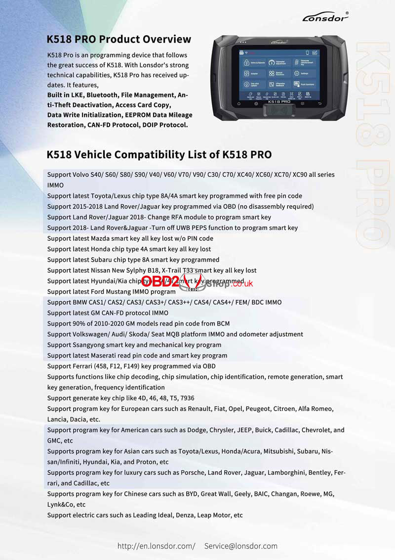 GODIAG ECU GPT Boot AD Adapter can work with J2534 devices to read and write ECU data by OBD2/GTP bench or boot method. Since not all ECUs can read and write without dissembling through the OBD2 interface, that's why the GODIAG adapter is designed to support 3 modes. 1. OBD2 Bench mode 2. GPT Bench(no disassembling) mode 3. Boot CNF1 read ECU mode 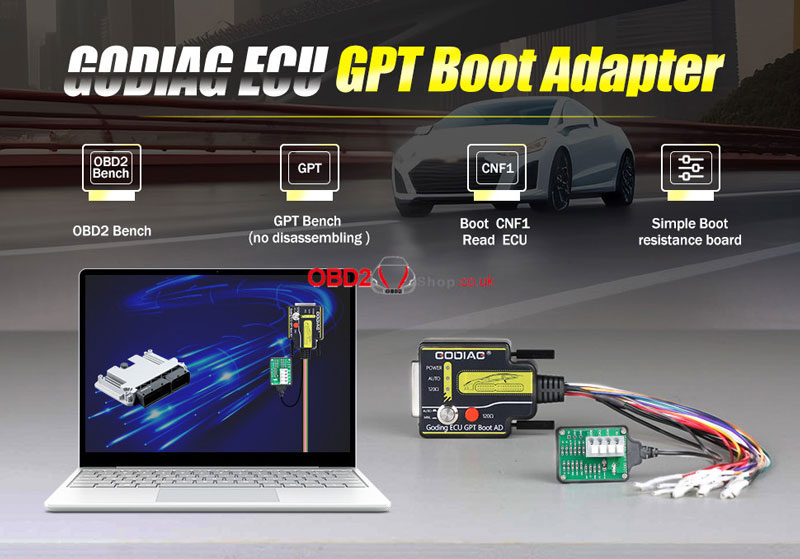 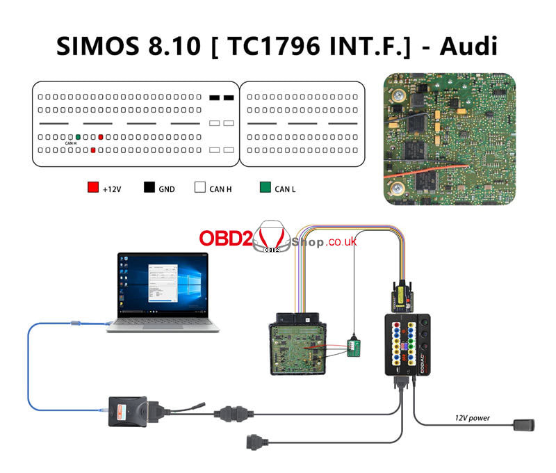 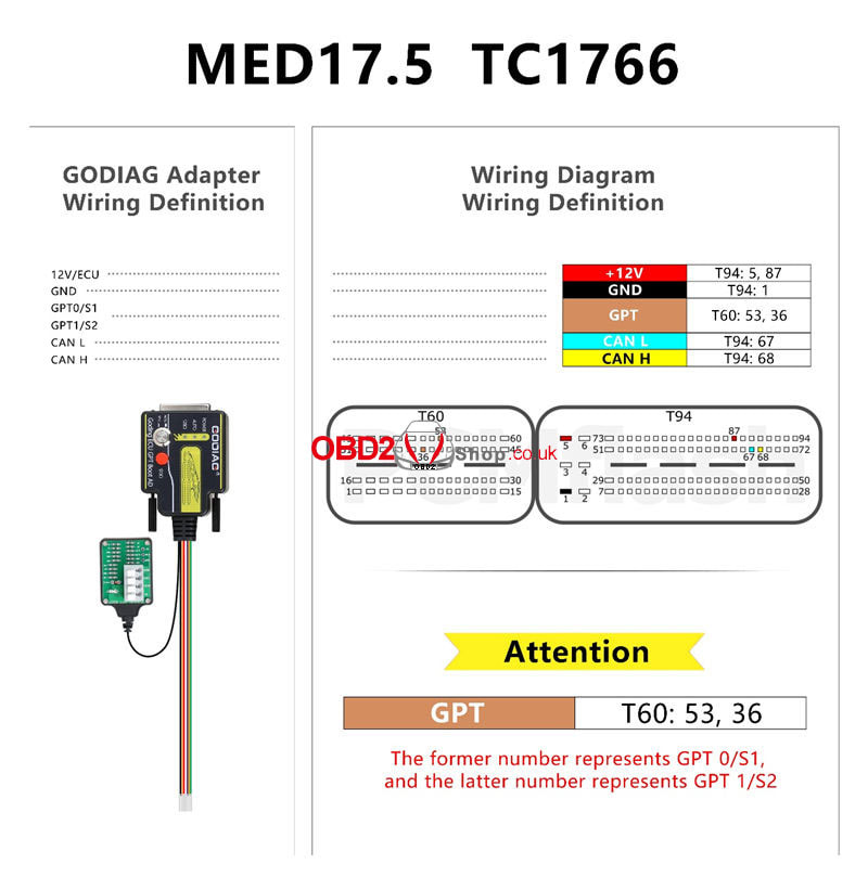 DIMsport KESS V2 KTAG connection diagram: 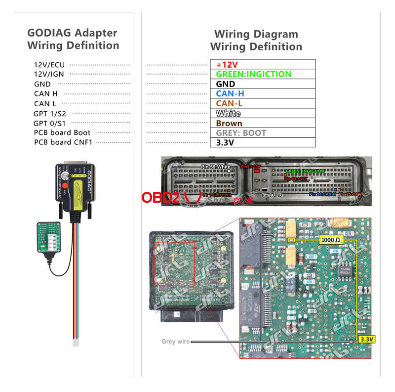 EVC ECU connection diagram: https://www.evc.de/en/product/bsl/ecu.asp Connect the L port to the boot port of the GODIAG ECU Adapter, and the H port to CNF1. 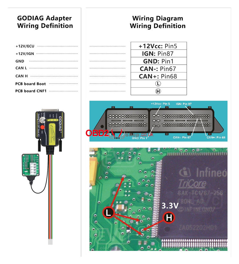 KT-PROG or FOX FGtech ECU connection diagram: https://www.kt-prog.com/download/ Connect the gray line to the Boot, CNF1, or 3.3V to 1KΩ resistance point, or follow the wiring diagram. Connect the brown line to GPT10, and write the line to GPT1.  OBDtuning ECU connection diagram: https://wiki.obdtuning.de/index.php/Hauptseite Support OBD2, GPT, and Boot mode without dissembling.  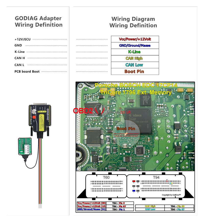
The previous article introduced that there are three ways to connect ACDP-2: Android, iOS, and PC.
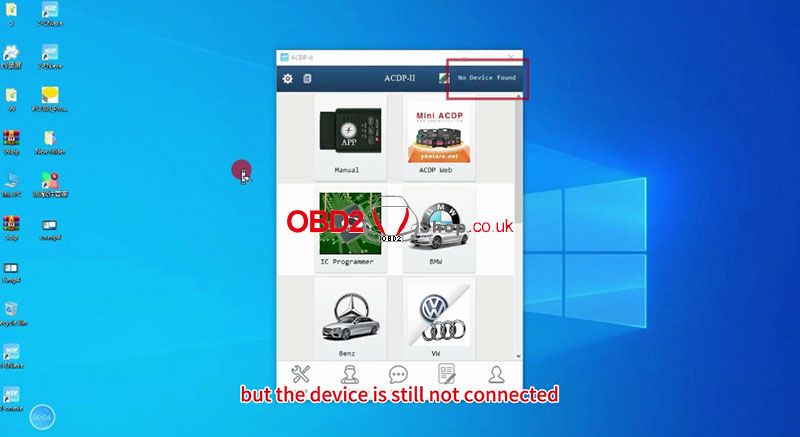
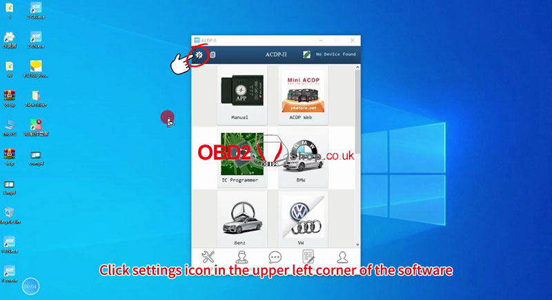
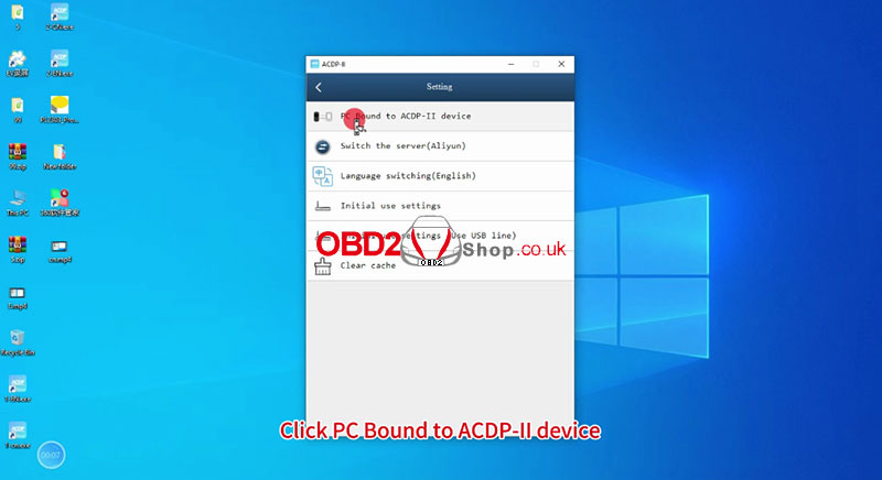
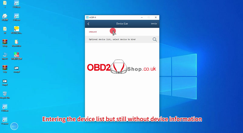
For specific connection methods, please refer to the article: Connect Yanhua Mini ACDP-2 to Android/iOS/PC via USB Cable This article will tell you how to fix the problem when ACDP-2 fails to connect to the computer via a USB cable. The situation where ACDP-2 connected to a computer via USB cable failed: When the ACDP host is connected to the computer and then you open the ACDP 2 software on the PC, it shows that the device is not connected. Click the "Setting" icon in the upper left corner of the software, then "PC Bound to ACDP-II device", and we can see the device list without any device information. 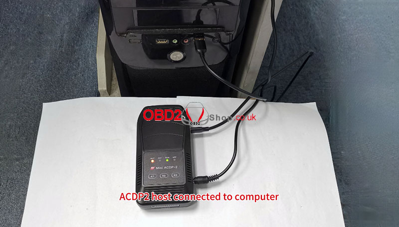
How to solve it:
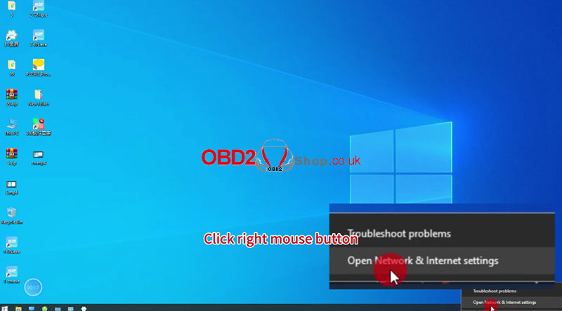
This situation can be achieved by changing the device IP and connecting to the device. Step 1. Move your mouse over the network icon in the lower right corner of your computer, then right-click and select "Open Network & Internet Settings". 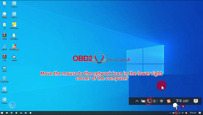
Step 2. Click "Change adapter options".
If you don't know which network ACDP is active on, you can unplug the USB interface connected to the device to confirm. 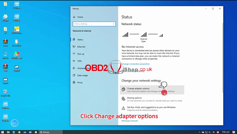
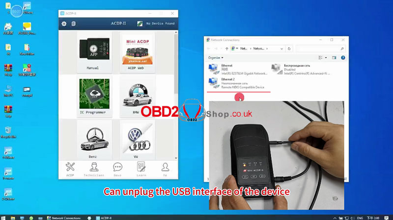
Step 3. Move the mouse over the device network.
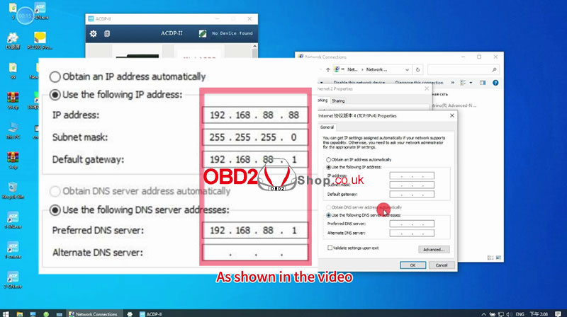
Right-click and click "Properties." Choose "Internet TCP/IPv4" >> "Use the following IP address:" Enter your IP address and DNS, as shown below, and click "OK" to continue. 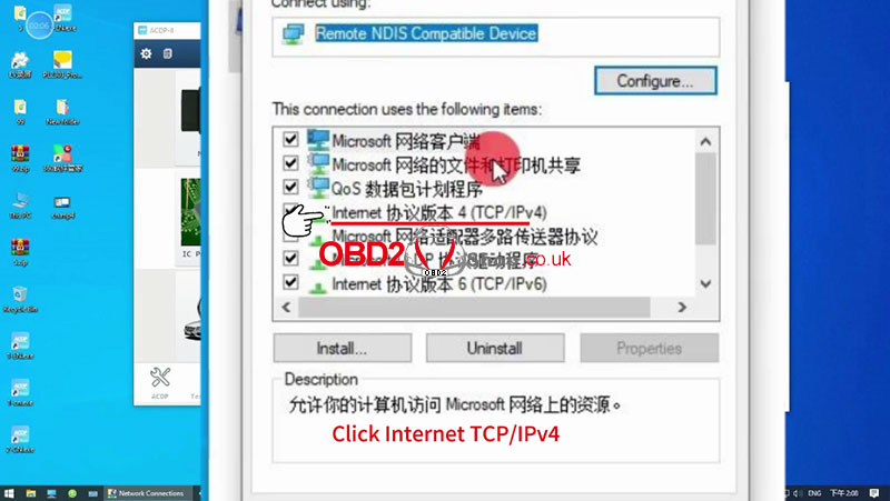
Wait a few seconds before the device automatically connects.
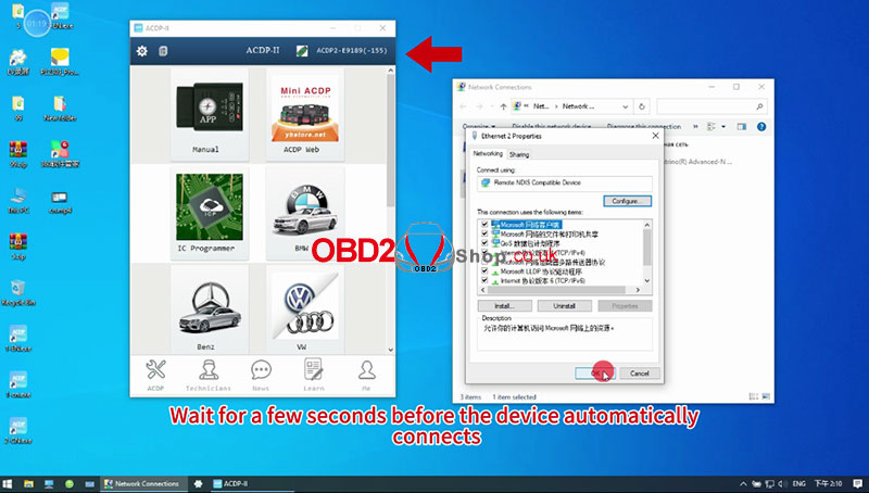
Done!
For detailed operations, please refer to
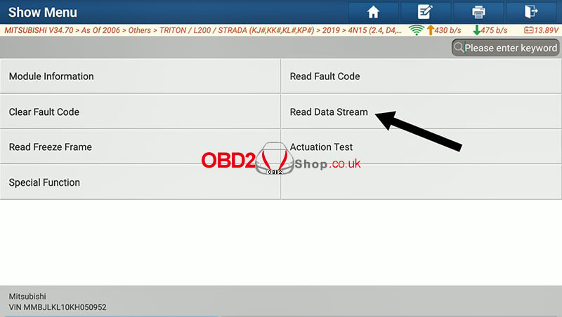
This post will guide you on how to use Launch X431 PAD VII/PAD V to perform steering angle sensor calibration for your 2019 Mitsubishi Triton.
Procedure: Open the X431 APP to identify vehicle information. 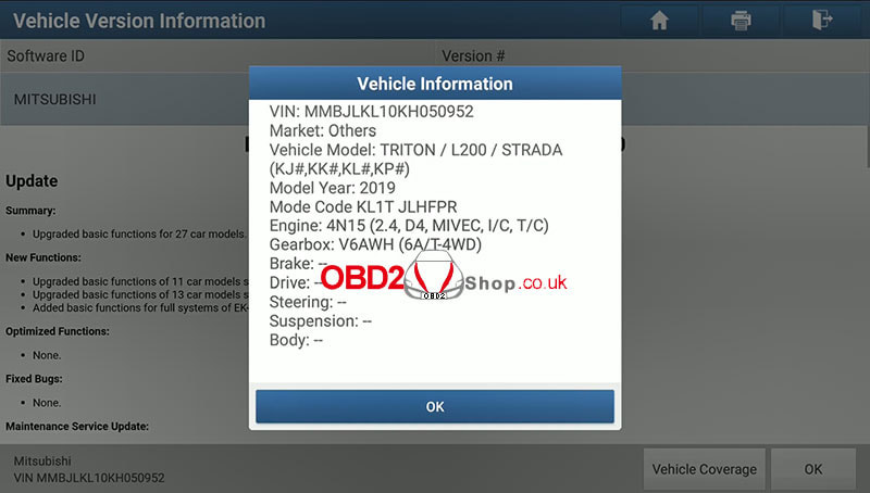
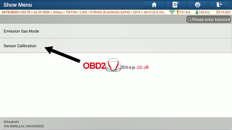
Then click back and select "Service Function".
The following error has been recognized, click "Enter" to continue. 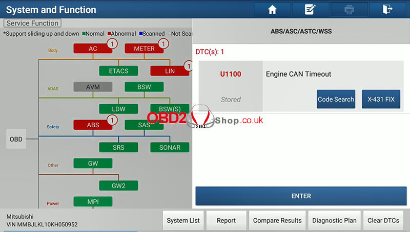
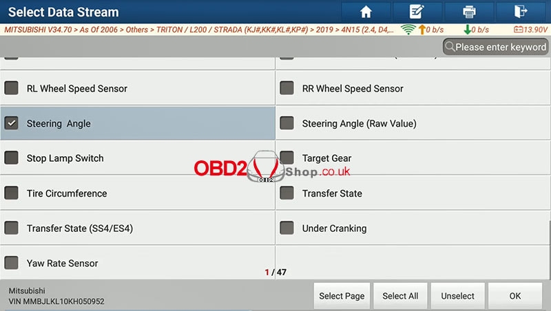
Select "Read data stream" >> "Steering angle" and click "OK" to continue.
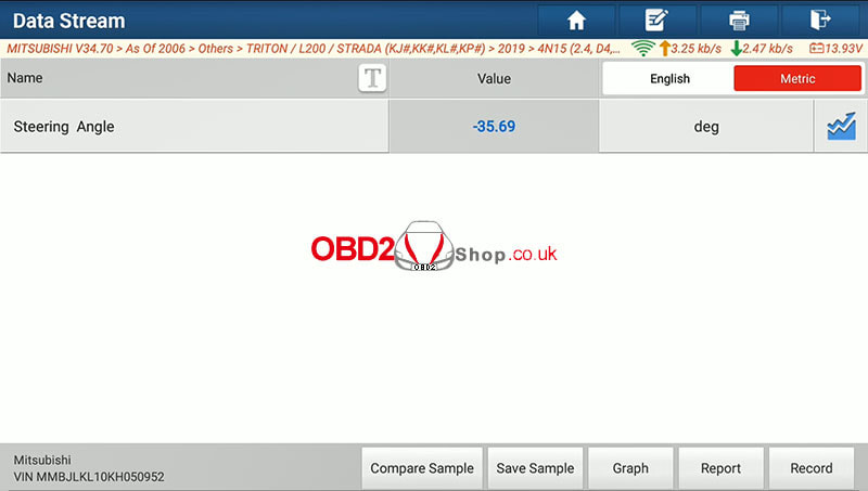
Turn the steering wheel to make sure it works.
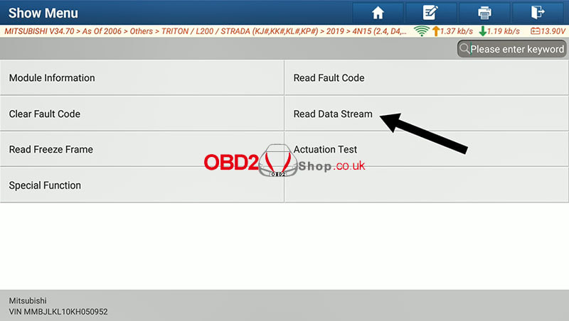
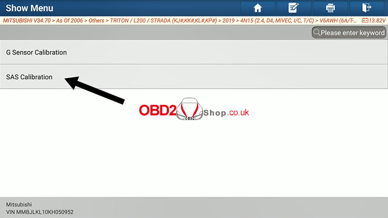
Go back and select "Read data stream" again and click "Sensor Calibration" >> "SAS Calibration".
"Are you sure to perform this function?" Click "Yes" to continue.
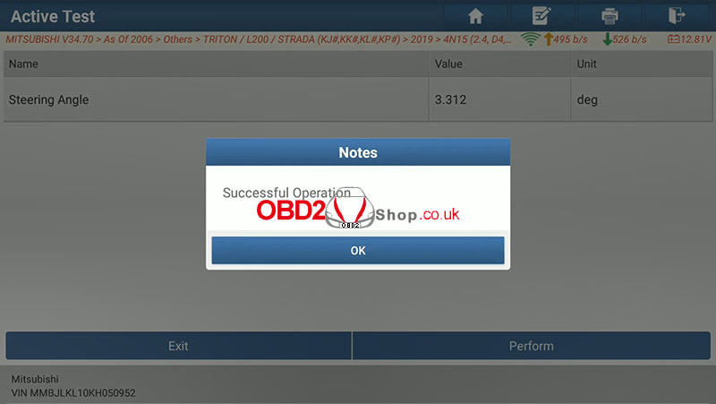
Initializing Communication, please wait... Use X431 Pad VII to calibrate the steering angle sensor of your 2019 Mitsubishi Triton successfully. 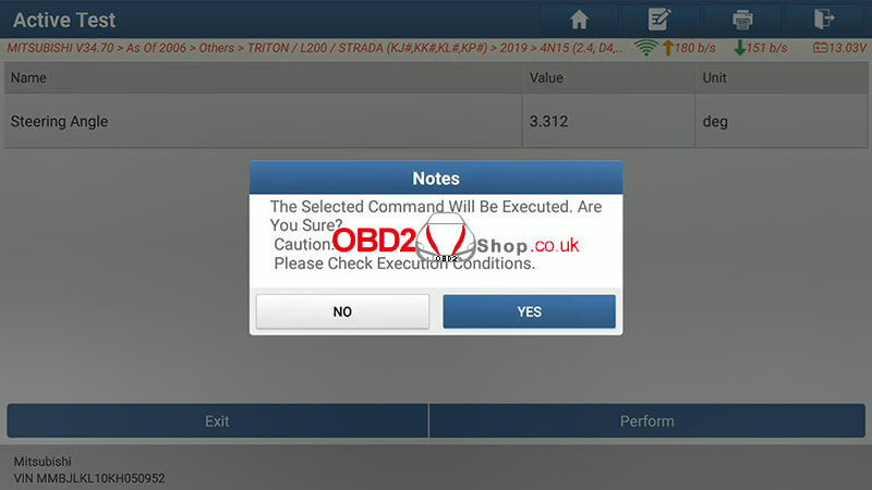
Video Guides:
2023 upgraded version Lonsdor K518 PRO pre-order is now available and will be coming in November. What is the latest tool new and different from the old Lonsdor K518? Here we've listed a comparison table for reference. 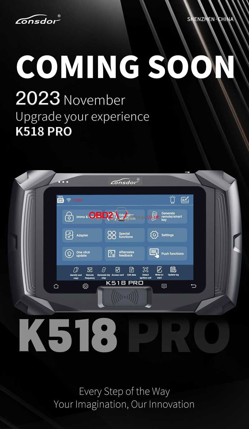 K518 Pro vs. K518ISE Comparison 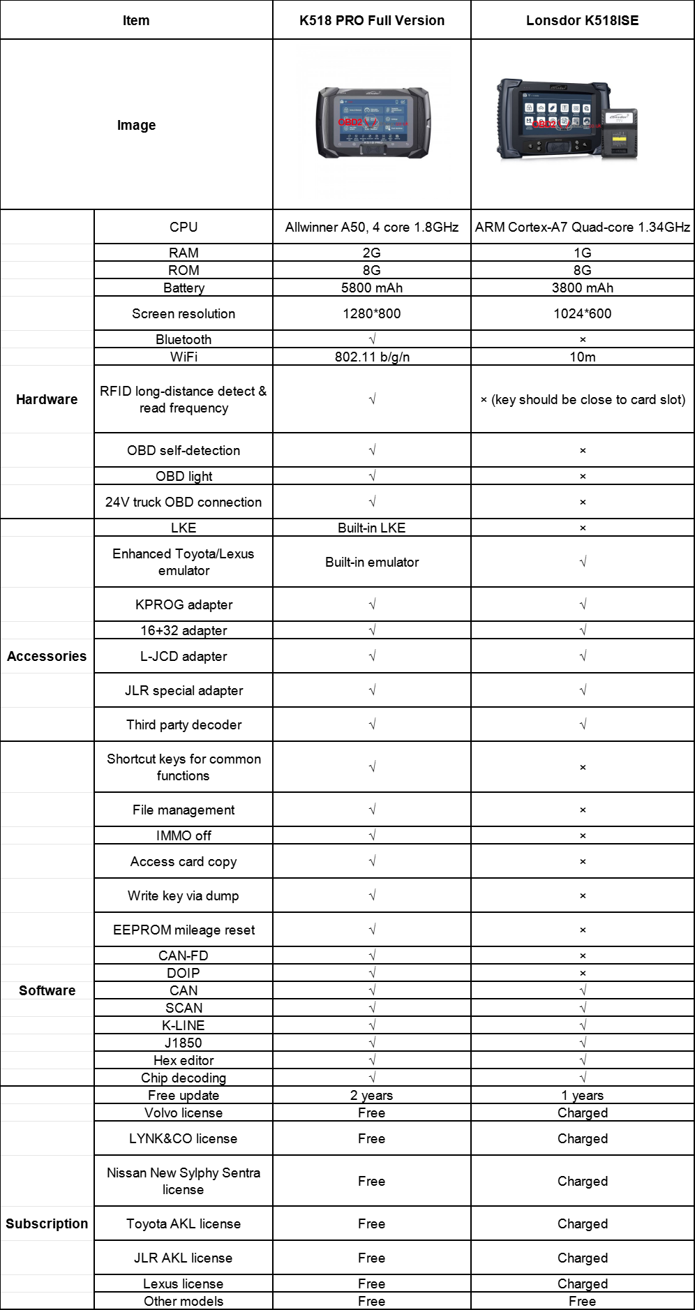 New & Different Feature
This post will guide you on how to use the OBDSTAR P50 Airbag Reset Tool to do a Toyota 89170-06790 airbag reset by bench.
Preparation: P50 Main Cable P004 Jumper + P004 Adapter Toyota 89170-06790 Airbag ECU 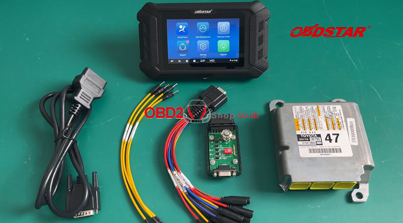
Procedure:
Please keep P50 in charge and communication throughout the whole process. Click "Airbag Reset" on the main interface, then select "Airbag Reset V30.48" >>"Brand" >> "Toyota". 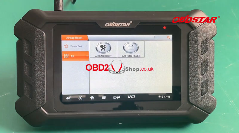
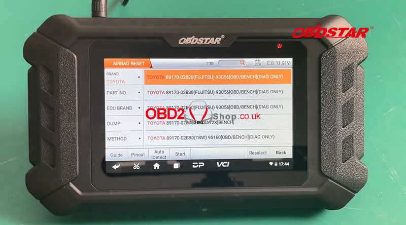
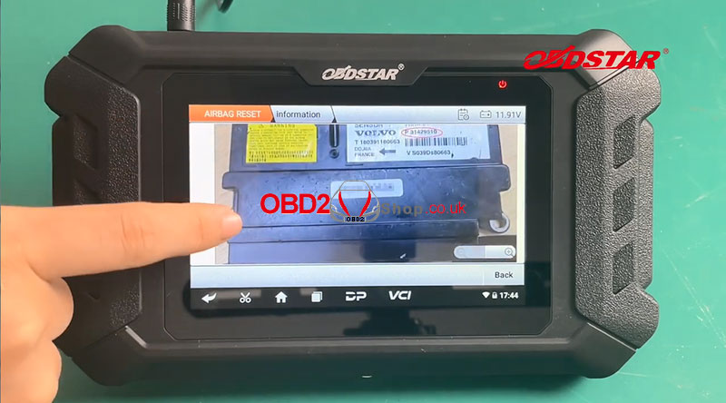
Check the part number on the ECU label.
Input the part number of ECU (case insensitive, fuzzy search supported) Remarks: Click operation instructions at the bottom left to check the best detection method. 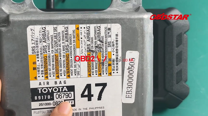
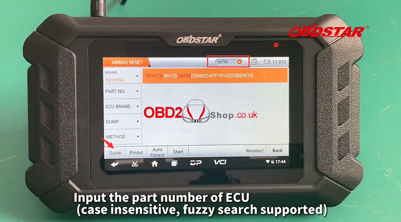
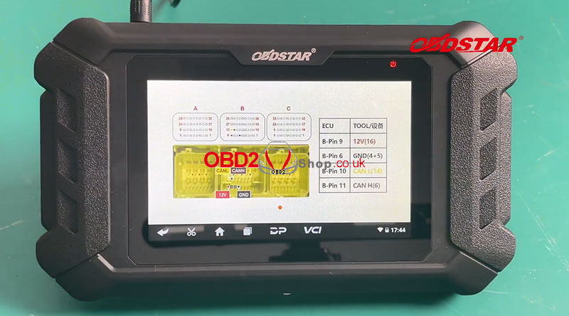
Click" Pinout"
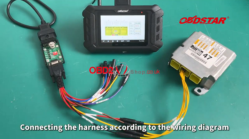
Connect the harness according to the wiring diagram, then click "Start" to continue. 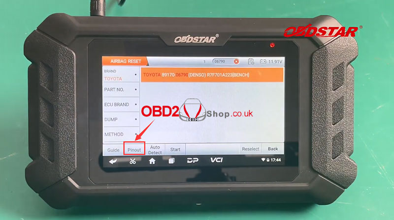
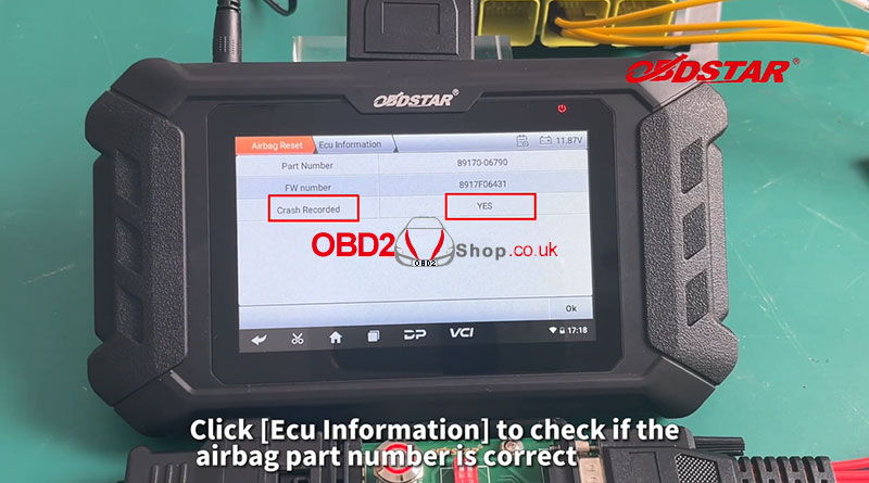
Click "ECU information" to check if the airbag part number is correct.
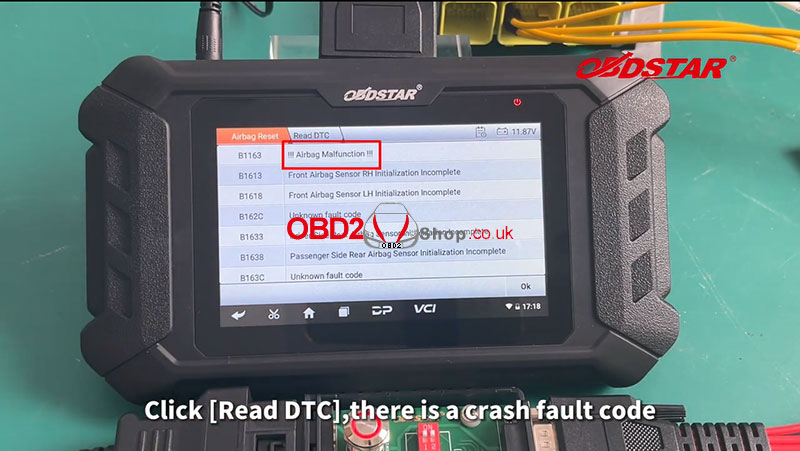
Click "Read DTC", there is a crash fault code, then we click "Erase Crash" to perform the operation. This function is available by connecting the server, please ensure the internet connection is normal. Erase Crash success. 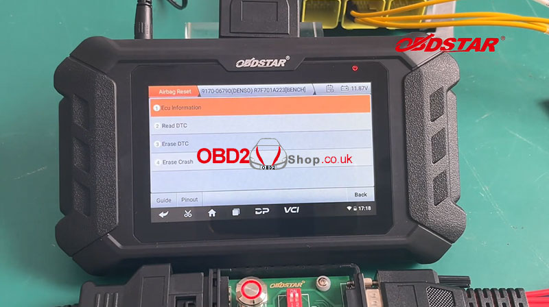
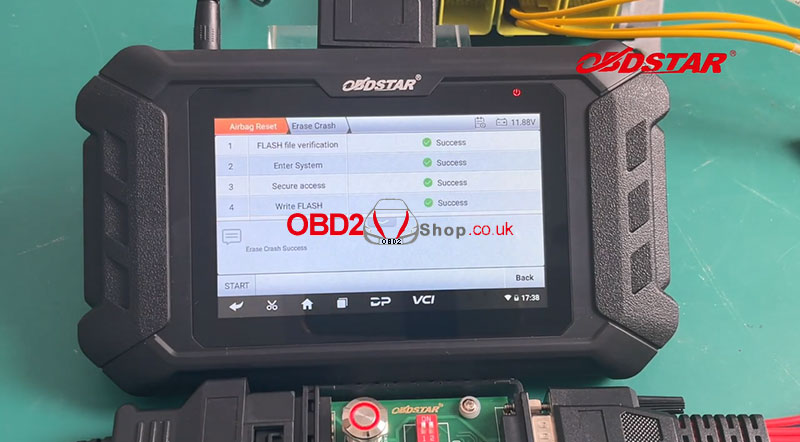
After the operation is done, read DTC again.
No crashfault code! The airbag reset is done! 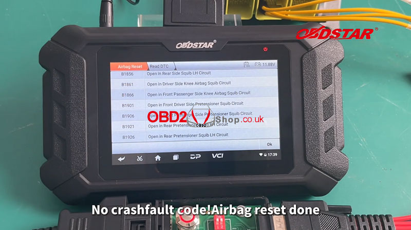
Video Guides:
How to clone BMW MSV90 with Launch X431 ECU & TCU Programmer by bench? Read this article to learn the operation. Users can follow the same steps if have an X431 X-PROG3 + PC Adapter instead. Open X431 ECU & TCU Programmer software, Search or select ECU model: MSV90 BMW, 1 series 2004-2011, N52B30A 130i 258, MSV90 TC1796 ECU Click "Direct connection of diagram" to check the wiring diagram. 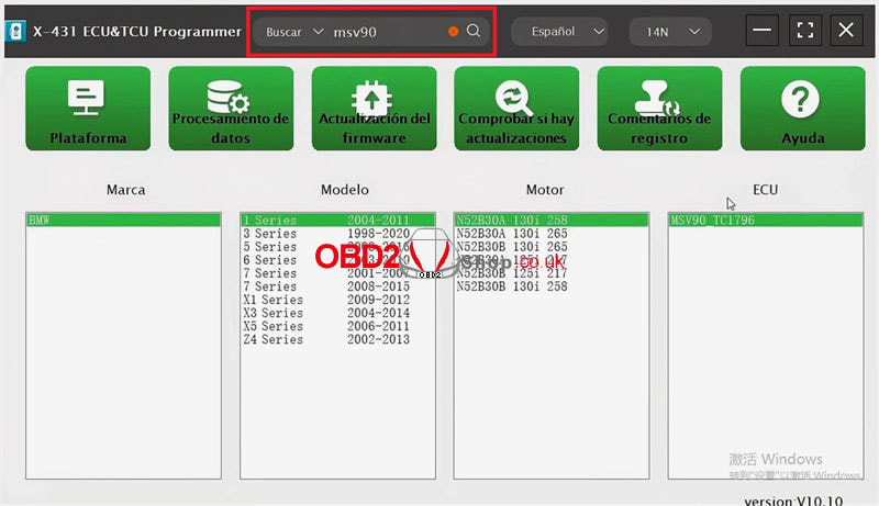 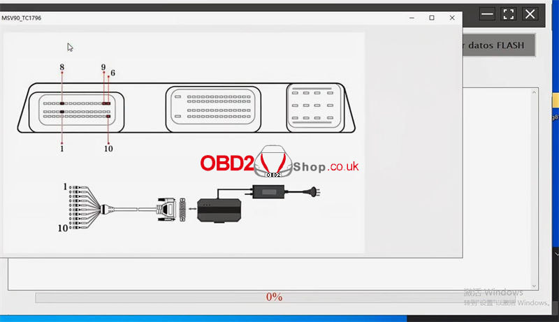 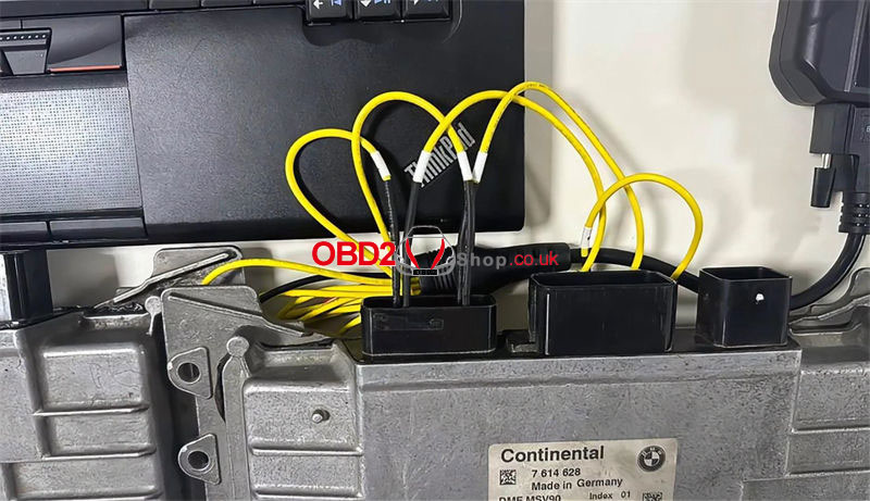 Click "Connect" to connect the device. Click "Read EEPROM data". Save EEPROM data. Click "Read FLASH data". Save FLASH data. Click "Disconnect" to re-connect the external ECU computer. Click "Connect". Click "Read EEPROM data". Save EEPROM data. Click "Read FLASH data". Save FLASH data. Click "Write EEPROM data". Load EEPROM data file. EEPROM data was written successfully. Click "Write FLASH data". Load the FLASH data file. FLASH data was written successfully. 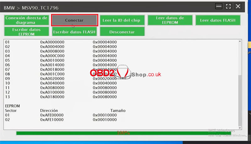 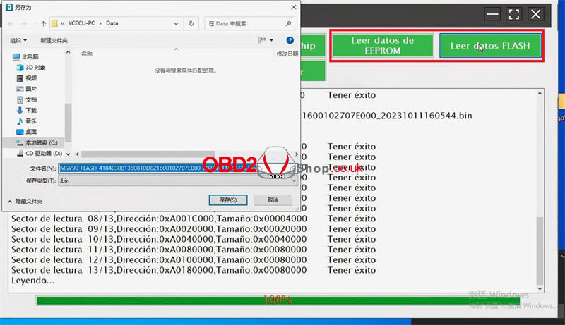 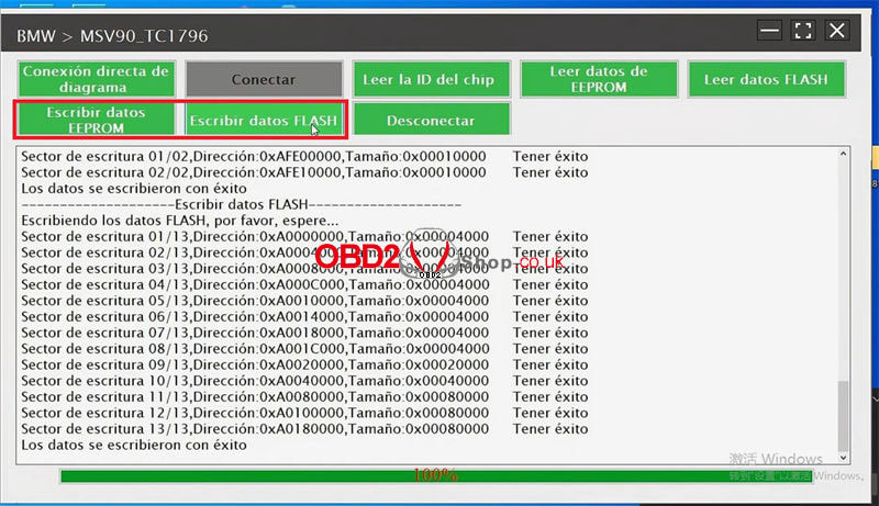 Click "Read chip ID". Check if the ID is the same as the original car computer. Click "Disconnect" when completed. Done. 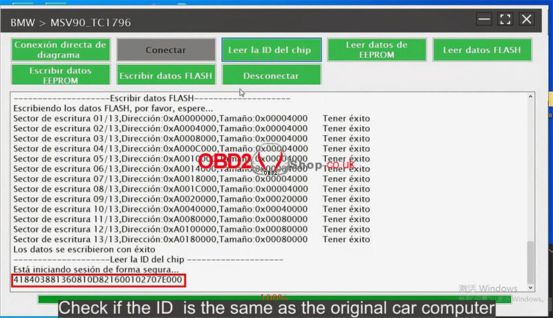 Autel CAN FD adapter can expand the support of the CAN FD protocol to specifically support the diagnosis of some new models, such as 2020 GM models. The CAN FD Adapter must be used with a supported Autel Vehicle Communication interface (VCI) to communicate with applicable vehicles. 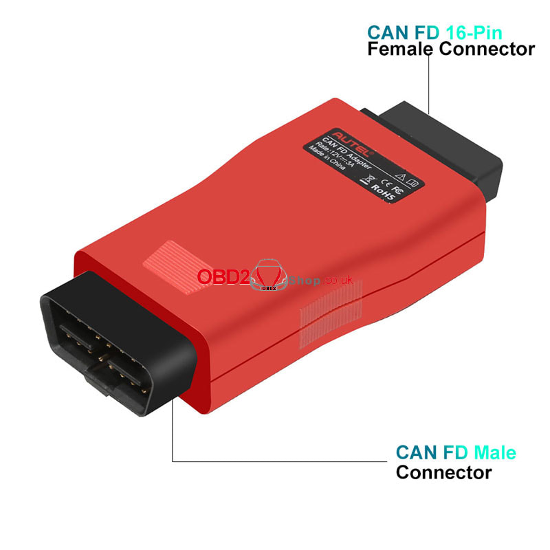 IMPORTANT: 1. The CAN FD Adapter is currently compatible with Autel's MaxiFlash Elite J2534-VCI, Wireless Diagnostic Interface, VCI 100, and VCI Mini. 2. Prior to use, update the VCI with the latest firmware. VCI update please refer to How to update your Autel V200 VCI There are two connection methods, you can select one based on the type of VCI device you have. 1. MaxiFlash Elite J2534-VCI/Wireless Diagnostic Interface: ① Connect the main cable's female adapter to the Vehicle Data Connector on the VCI unit, and tighten the captive (thumb) screws. ② Connect the CAN FD adapter's 16-pin female connector to the main cable's male adapter. ③ Connect the attached CAN FD adapter to the vehicle's DLC, which is generally located under the vehicle dashboard. 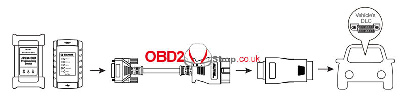 2. VCI 100/VCI Mini: ① Connect the CAN FD adapter's 16-pin female connector to the Vehicle Data Connector on the VCI unit. ② Connect the attached CAN FD adapter to the vehicle's DLC, which is generally located under the vehicle dashboard. 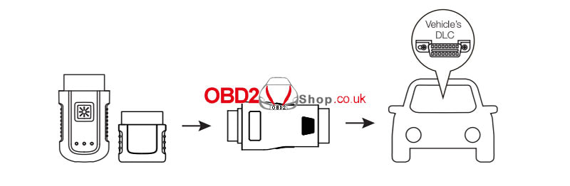 This is a tutorial on how to read and write Ford 6000CD radio code with OBDSTAR DC706 by bench. It can also support to clone EEPROM. Read this article to learn step by step. Accessories DC706 ECU Tool P004 ECU Clone Adapter + Jumper Main cable Ford 6000CD Please keep DC706 charging and communicating during the whole process. 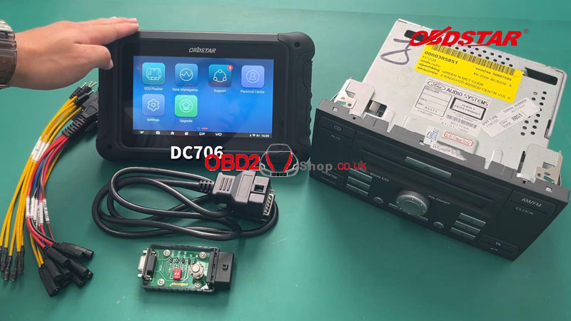 Operation ECU Flasher >> BODY/ CHASSIS/ OTHER >> Latest version >> BRAND >> FORD >> FORD RADIO VISTEON 6000CD TMS470(OBD/BOOT) Press "Guide/Pinout" to check the best detection method. Connect the harness according to the wiring diagram. 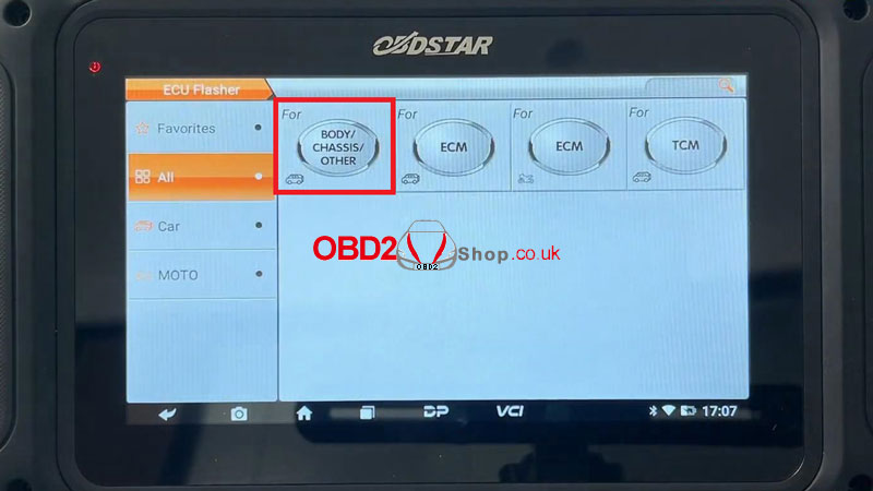 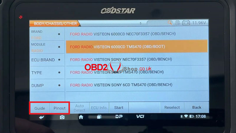 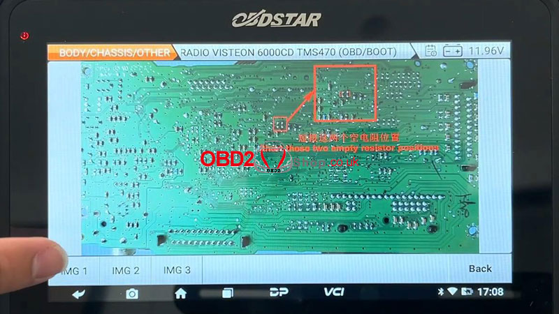 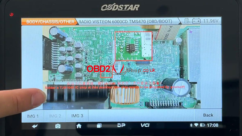 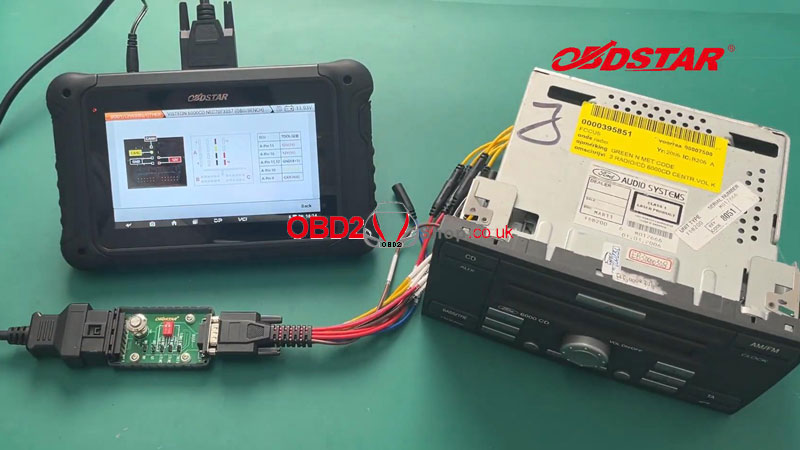 After a successful connection, press Start >> OBD >> OK This function is available by connecting the server, please ensure the Internet connection is normal. Switch on P004 ignition. Press "Code Read". Writing bootloader... Pincode read successfully:1234 Reboot and enter the pincode on Ford 6000CD radio for verification. Pincode verification is successful. Press "Code Change" to change the pin code: 4321 Operation success. Reboot and verify the changed pincode on the 6000CD radio. Pincode changed successfully. Press "Code off". Security verification in progress... Operation success. 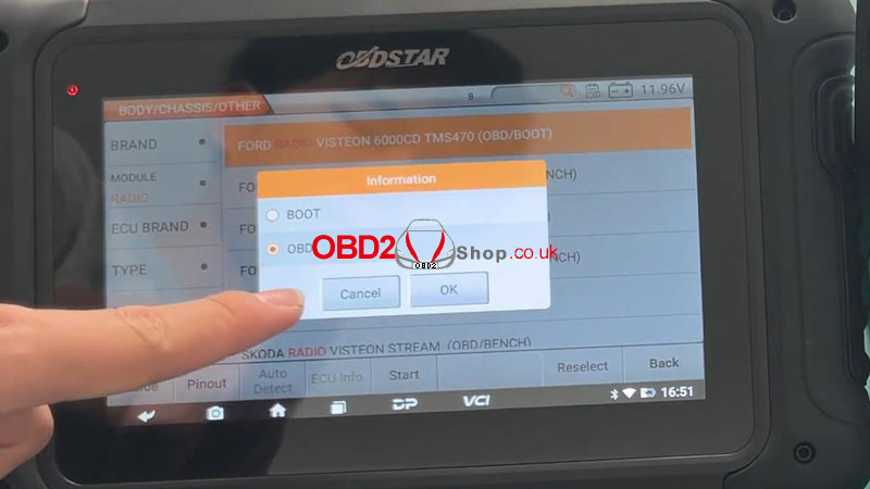 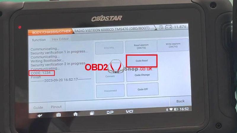 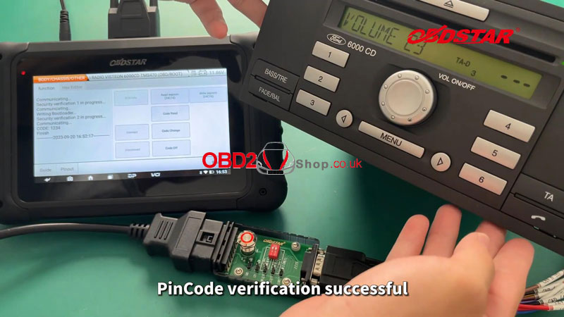 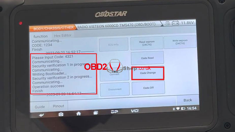 Next, we can also read/write EEPROM (24C16) for radio ECU cloning. Save EEPROM's success. WriteEEPROM(24C16) >> Load external data Writing EEPROM... Writing success. The read-and-write EEPROM operation is completed. 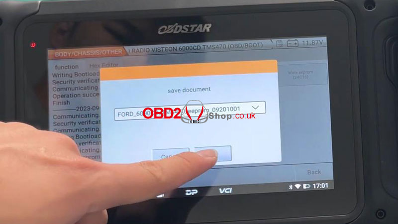 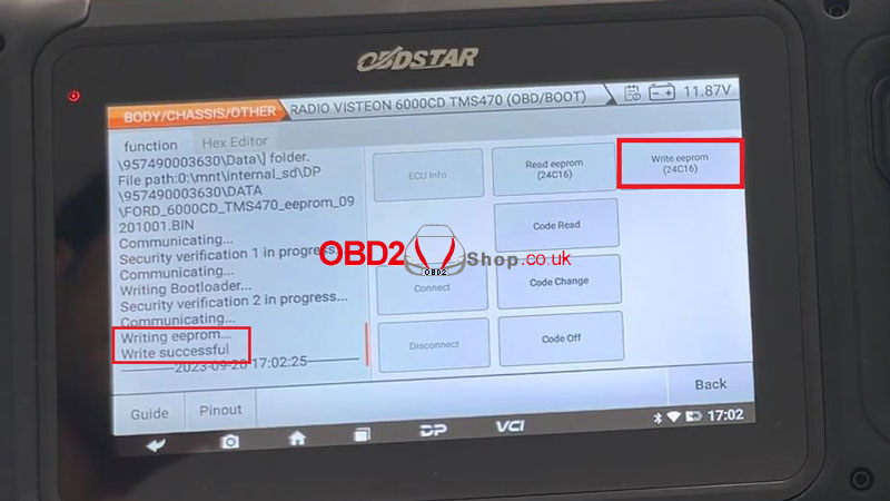 |
