|
This is a tutorial on how to use Yanhua Mini ACDP 2 + Module 31 to add keys for the BMW F chassis BDC 085 version via OBD(DoIP method).
Check the video for full operation:
Procedure:
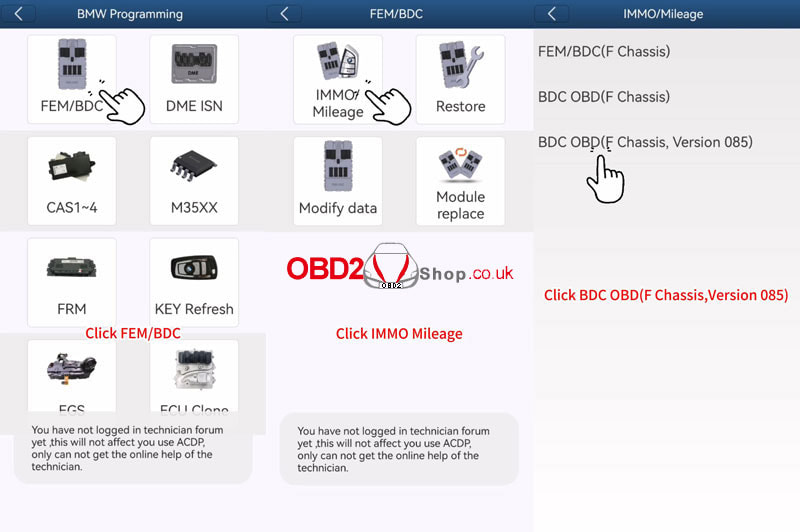
Connect Mini ACDP & OBDII interfaces with Module 31 DoIP adapter. Open the Mini ACDP app. The device number displayed in the top right corner indicates successfully connected. BMW >> FEM/BDC >> IMMO/Mileage >> BDC OBD(F chassis, Version 085) >> Detect vehicle info Please use the ACDP standard power adapter(voltage+12V, current >= 2.5A) Connect ACDP with vehicle OBDII port! Please save the vehicle system data. Check vehicle info is normal. Identify vehicle info finish. 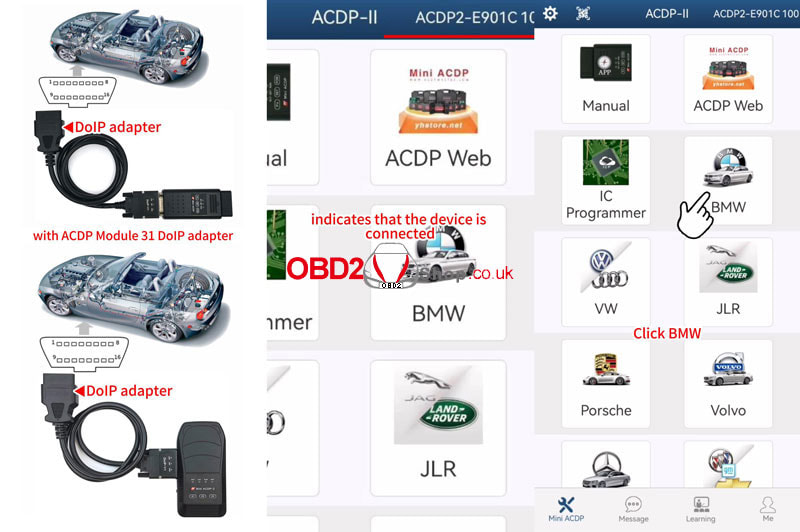
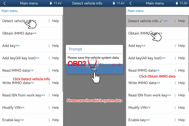
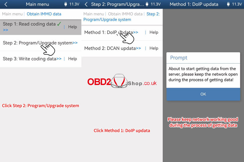
Obtain IMMO data >> Read coding data >> OK
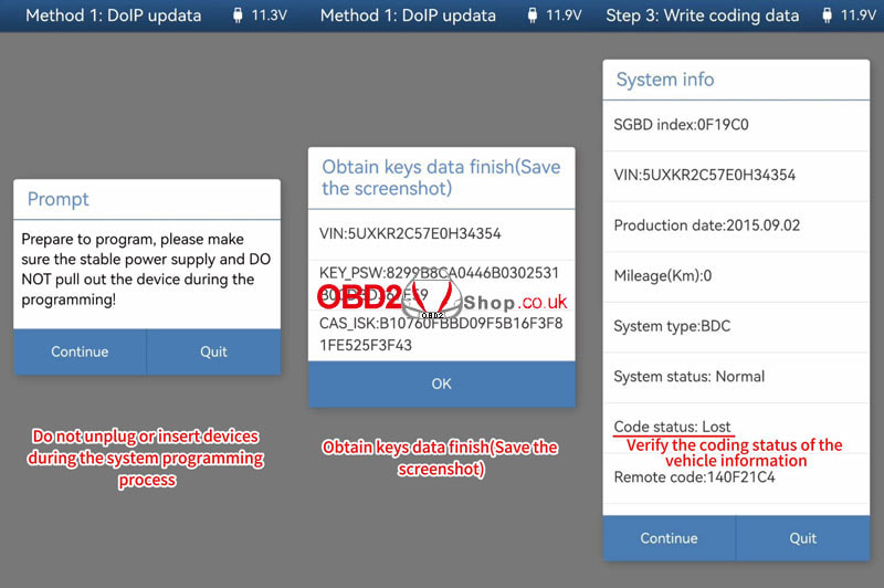
Connect ACDP with vehicle OBDII port! Check vehicle info is normal. Please save coding data. Read coding data finish. Program/Upgrade system >> DoIP update >> OK >> Continue Please save the vehicle system data. The backup file succeeded. Check vehicle info is normal. About to start getting data from the server, please keep the network open during the process of getting data! Prepare to program, please make sure the stable power supply and DO NOT pull out the device during the programming! Programming ECU, please wait... Please save key data. Obtain keys data finish. Write coding data >> OK >> Continue Verify the coding status of the vehicle info. If it's a lost state, click "Continue" to restore it. If it's a normal state, click "Quit". Please select coding data. Writing coding data, please wait... Write coding data finish. 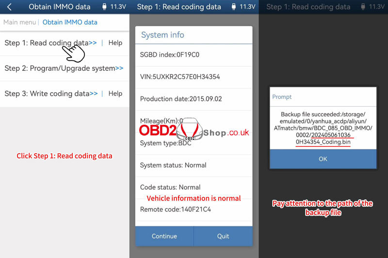
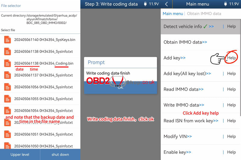
Click "Add key Help".
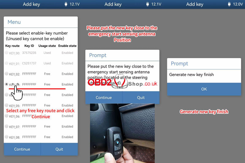
1. Connect ACDP to OBDII, when using Mini ACDP-2, it's necessary to change the Diop cable to the OBDII extension cable. 2. Connect the BAV-KEY adapter to the ACDP-2 device properly. 3. Place the working key into the BAV-KEY adapter properly. Add key >> OK >> Continue Vehicle info is normal. Please select key data. Confirm the working key has been correctly placed in the BAV-KEY adapter. Please save ISN data. The backup file succeeded. Take a screenshot or click "Export" to save IMMO info. Select any free key position, and click "Continue." Please put the new key close to the emergency start sensing antenna position(located at the steering wheel's right hand). Learning new key... Generate a new key finish. Remember to check whether the new key functions properly. Done. 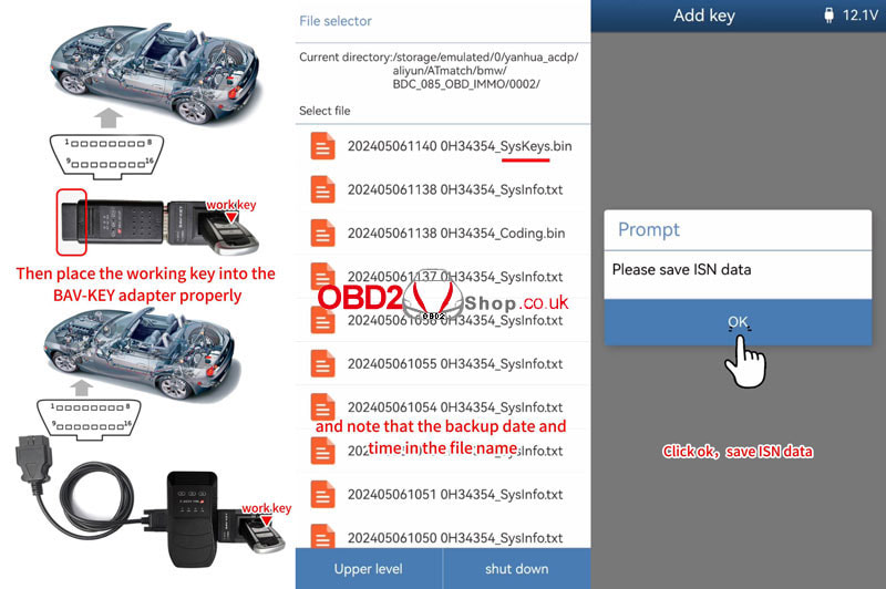
0 Comments
This is a tutorial on how to use Yanhua Mini ACDP-2 + Module 33 to add a smart key for the Volkswagen 4.5th generation MQB(3526+95320).
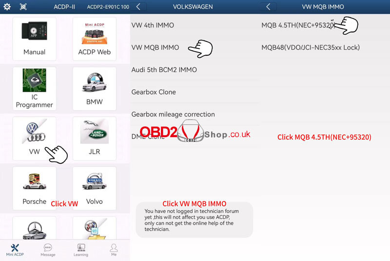
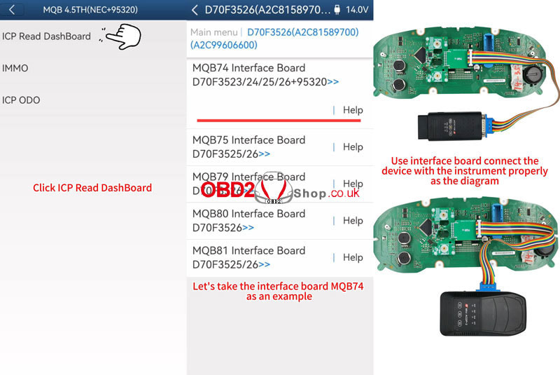
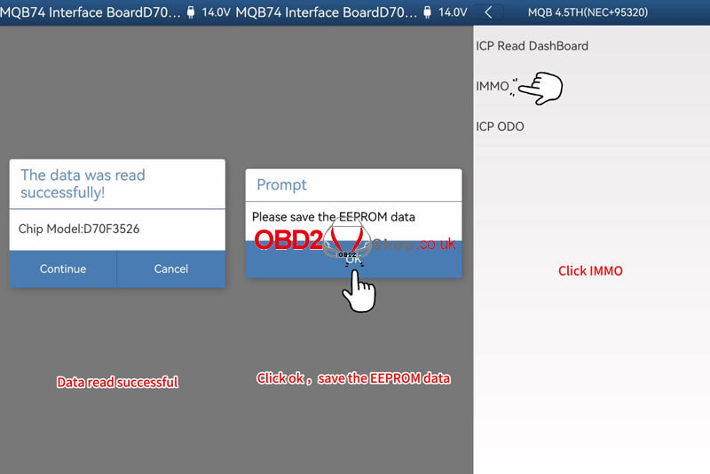
Remove the instrument cluster from the car and open the cluster shell to check the chip model. Power on Mini ACDP-2. Open the Mini ACDP app. Confirm the SN is showing in the upper right corner, which means the device is connected to your phone or PC. VW >> VW MQB IMMO >> MQB 4.5TH(NEC+95320) >> ICP Read Dashboard >> D70F3526(A2C81589700)(A2C99606600) >> MQB74 interface board D70F3523/ 24/ 25/ 26+95320 *Click "Help" to check the connection diagram. Please use the ACDP standard power adapter(voltage+12V, current >= 2.5A). Please connect the main unit and the meter. Continue >> Continue Data read successfully. Please save all backup data of the chip. OK >> OK Please save the EEPROM data. Reinstall the instrument panel into the vehicle and confirm that the vehicle is functioning properly. 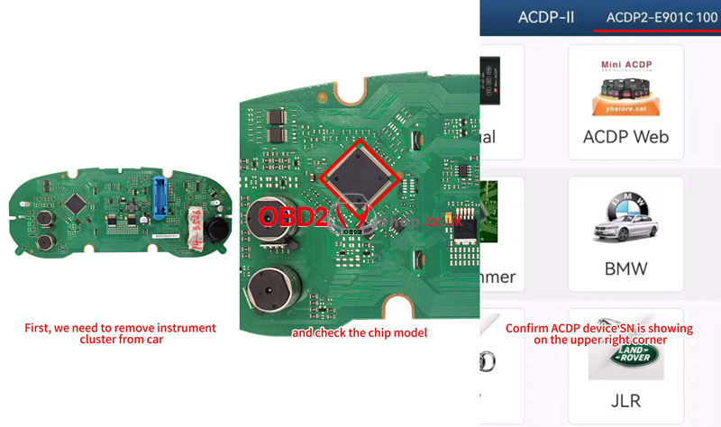
IMMO >> Step1: OBD identify Help
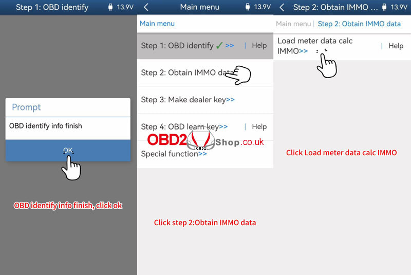
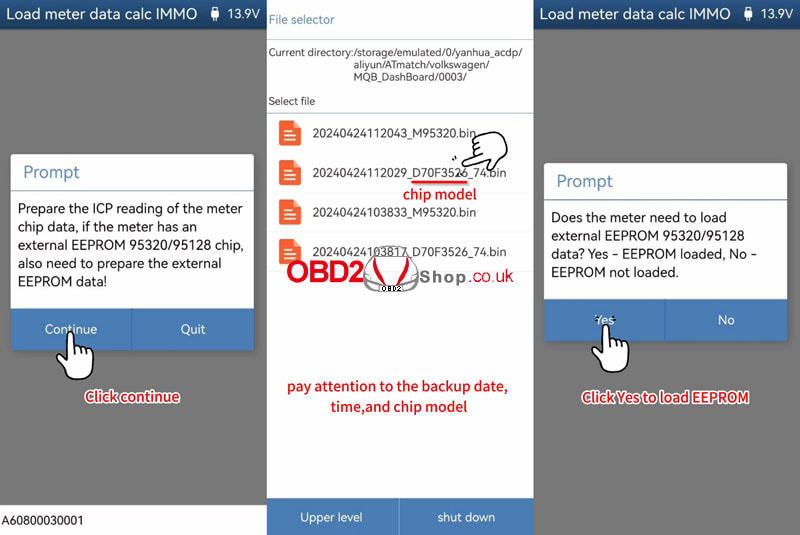
Connect the ACDP to the vehicle's OBDII port properly. Step1: OBD identify >> OK Connect ACDP to vehicle OBDII! If have a working key, please insert it to/near the ignition switch and light the meter! If all key lost, open the headlight and step on the brake! Continue >> OK OBD identifies info to finish. Obtain IMMO data >> Load meter data calc IMMO >> OK Prepare the ICP reading of the meter chip data, if the meter has an external EEPROM 95320/95128 chip, also need to prepare the external EEPROM data! Please select the NEC chip data for the instrument. Does the meter need to load external EEPROM 95320/95128 data? Yes - EEPROM loaded. Please select external EEPROM 95320/95128 data. The IMMO data will be calculated soon, please keep the network smooth during the data calculation! Please save IMMO data. OK >> OK >> OK Obtain IMMO data finish. 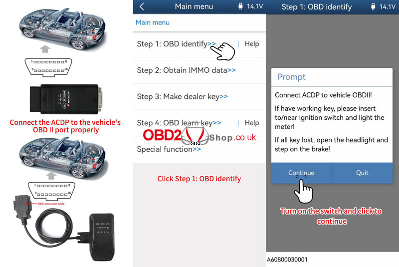
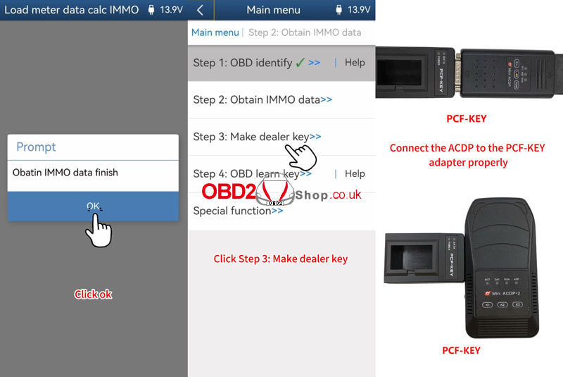
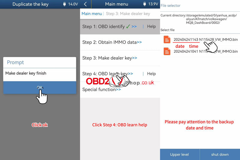
Make dealer key >> Duplicate the key >> OK
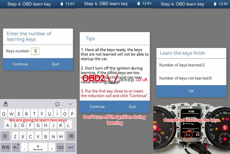
Connect the ACDP to the PCF-KEY adapter. Place the blank key that has been changed to the original car's lost key ID on the PCF-KEY adapter correctly! Note: the new key should be a blank key that ID can be changed and the blank key has been changed to the ID of the lost key. Place the blank key that has been changed to the original car's lost key ID on the PCF-KEY adapter correctly. Continue >> Continue Please select IMMO data >> Continue >> VW Programming key data is about to begin, and forbidden to power off or unplug the device during operation! Make dealer key finish. OBD learn key >> OK >> Continue >> Continue Please select IMMO data. Enter the number of learning keys: 2 Tips 1. Have all the keys ready, the keys that are not learned will not be able to start the car. 2. Don't turn off the ignition during learning, if the other keys are too close to the induction coil can may cause learning failure. 3. Put the first key close to or insert the induction coil and click "Continue". Put the 1st key close to or insert the induction coil, and click "Continue". Put the 2nd key close to or insert the induction coil, click "Continue". Number of keys learned: 2 Completed learning 2 keys. The smart key addition is complete. Please try on the car and verify if the added key functions are normal. 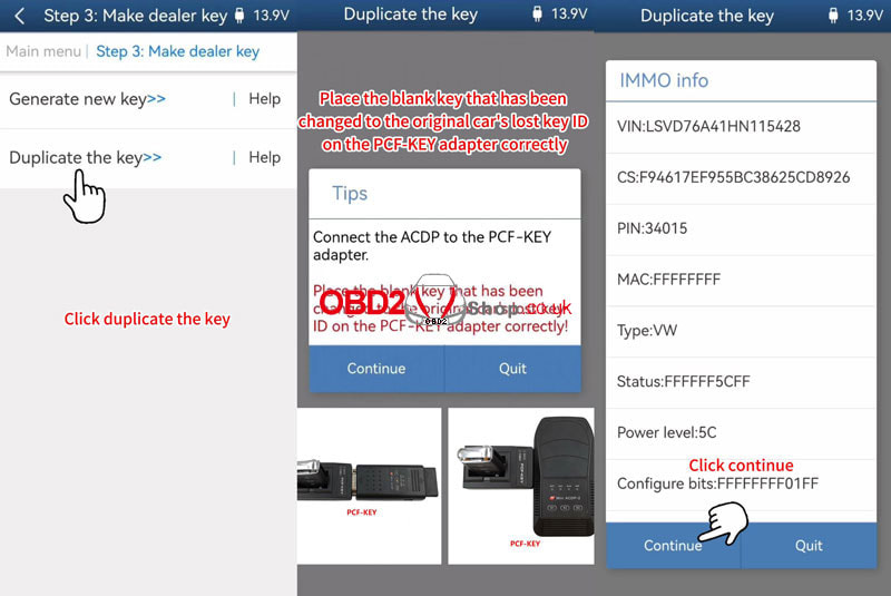
Video guides:
Customer's problem: I bought 10/2023 Cgpro v2.2.0.0 from you, I have issues with my device I cannot write mileage on 35160wt EEPROM, and it seems to not be able to initialize the device properly before writing new data to EEPROM. Is it possible to file a complaint about this to you? I even just tried increasing mileage by 2000km and trying to write backup Again, the same issue. Initialization error after 25 mins at 95%. Is new status, after messing around with it I can only read 16km dump out of my EEPROM. When it's soldered to the cluster it shows a mileage of 45019km. It looks like it cannot read the EEPROM any longer either..... 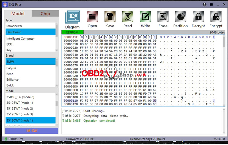 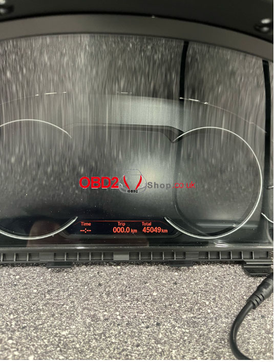 Solution: Chip heating or replacing the spare chip. 35160WT erasing heating method instructions (if the chip cannot be erased, you can try it): Before operation, adjust the air gun to 100°C and heat the chip for 20 to 30 seconds (the chip is soldered to the board). After that, stop heating and put it on immediately to try the operation. After waiting for the chip to cool down completely, if the chip has not entered the second stage for erasing, you can reheat it with an air gun for 20 to 30 seconds and then stop heating. The chip may be erased during the cooling process. Customer's feedback: I tried and tried and tried today and I found a method with a heat gun that finally worked! So now I have successfully written 16km to EEPROM. I will remember this method for next time and Hopefully, it'll last! I'm sorry for the inconvenience but please understand my anger when in the field and this didn't work. Have a great weekend! 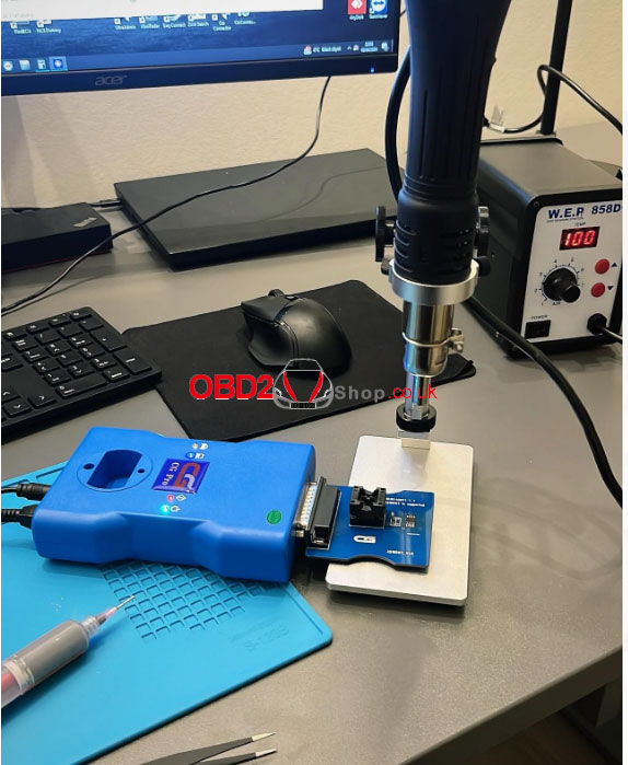 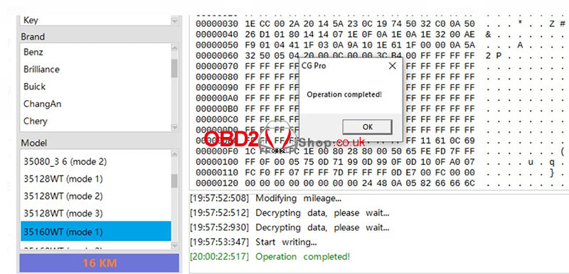 For more technical support, please follow www.obd2shop.co.uk
Lonsdor KW100 is smart and genius to help users generate smart keys without any chip type and frequency. Today we're gonna show how to use it to quickly generate a 2023 Toyota Camry with all keys lost & add keys. Generate 2023 Toyota Camry All Keys Lost Note: Please use the LT20 Smart Key and don't put any other keys nearby. Make sure the frequency detected from the car is accurate. Connect the KW100 Key Generator to a smartphone with the Lonsdor App downloaded. Quick generate >> Quick generate(AKL) >> Start Please slam on the brake, and press the Start button once every 5s or so. This function will take about 1-3 mins, please wait patiently... Acquired successfully Continue >> Select button, start to generate Place the LT20 smart key into the KW100 card slot, and press OK. Key generation is successful. 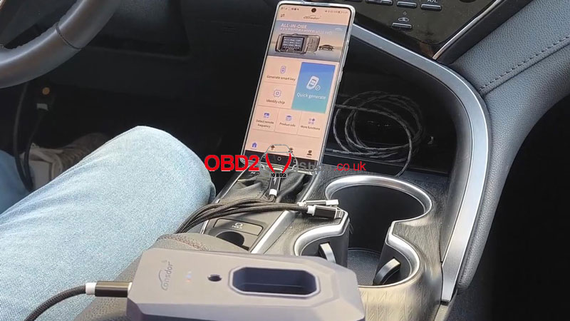 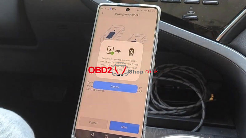 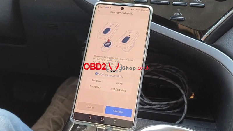 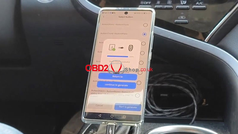 Generate 2023 Toyota Camry Key Adding Note: We cannot have any other keys nearby to make sure the frequency detected from the original key is accurate. Place the original key into the KW100 card slot. Quick generate >> Quick generate(with key) >> Start Next, we can use Lonsdor K518 PRO to program the key to this car. Acquired successfully Remove the original key, and put the LT20 smart key into the car slot. Continue >> Select button, start to generate >> OK Key generation is successful. Next, we can use Lonsdor K518 PRO to program the key to this car. 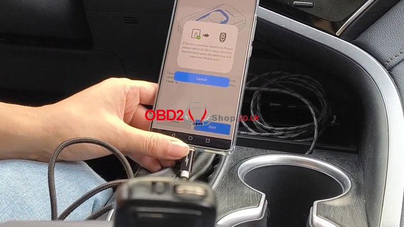 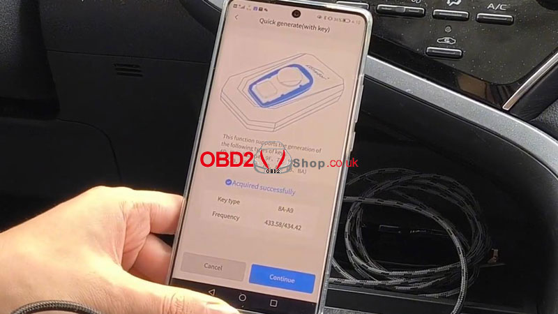 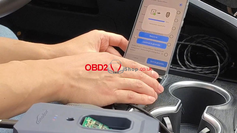  A new device Lonsdor KW100 was launched recently that should work with Lonsdor APP on a phone together. In this article, we'll how to download and use it. How to download Lonsdor APP? Please scan the QR code to download/update the details. After a successful download, we need to make a choice between BSKG & KW100, let's select KW100 here. 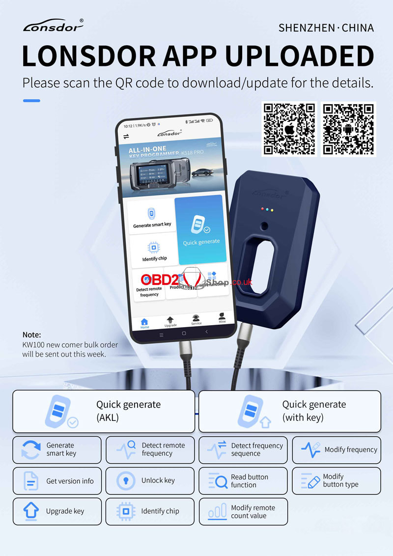 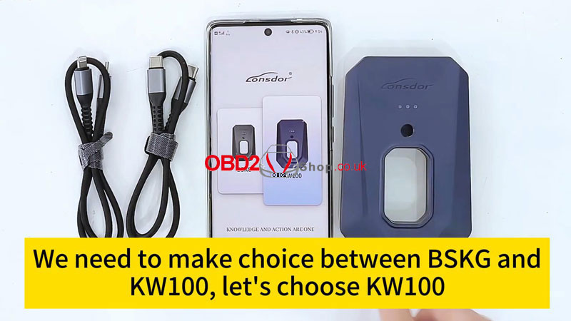 How to register & login Lonsdor APP? Click to Login >> Fast Login/ Account Login - If you have a Lonsdor device before, you can choose "Account Login" with your account and password. - If you never have a Lonsdor device, choose "Fast Login". The default password will be auto-set as 12345 after login. When you log in with your account next time, you can change the password by clicking "Forget Password" from "Account Login". Users can get all functions worked after login and registration. 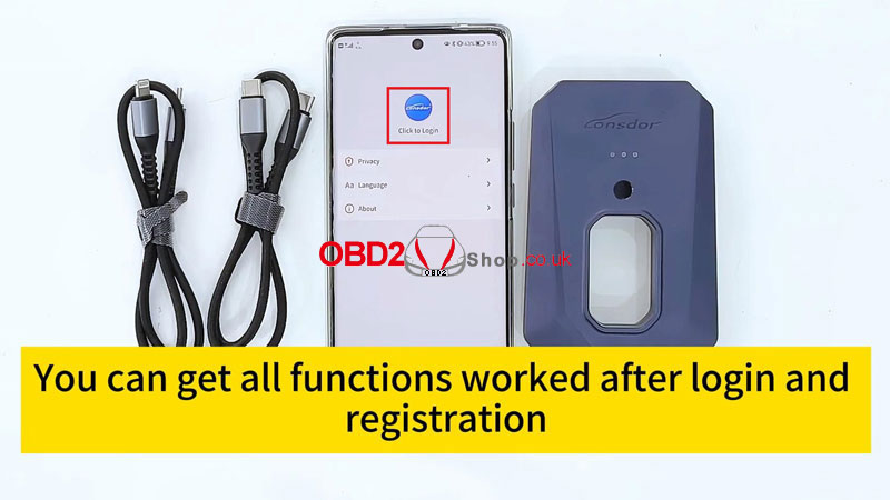 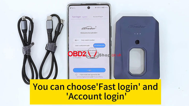 What functions are available on the Lonsdor APP? There are some important functions listed on the interface, so we can easier to find and use them. Generate Smart Key: Users can find the supported cars to generate the key. Lonsder now supports Toyota, Lexus, and Subaru. Users can easily search the car models with the name and year in the search bar. * All generations need to use the Lonsdor LT20 Smart Key. Users can follow the picture and tips to put the key. When you "Start to generate", it'll auto-search KW100 nearby and connect through Bluetooth. Quick Generate service for all users. It has 2 parts: Quick Generate(AKL) and Quick Generate(with key). Quick Generate(AKL) - for all keys lost. Quick Generate(with key) is for users who have keys. Users don't need to search or identify chip type and frequency individually for both generations. 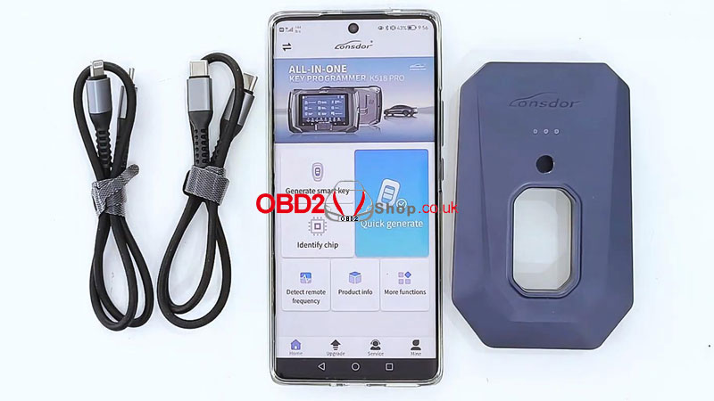 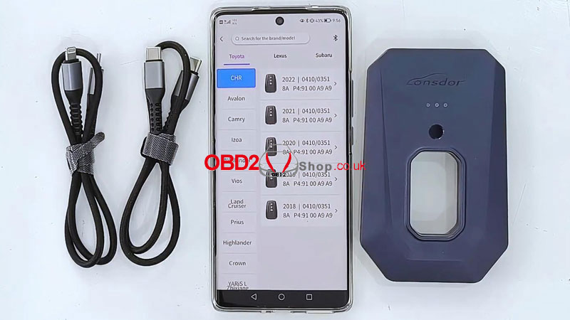 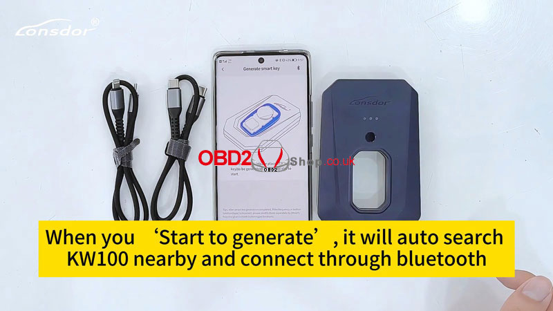 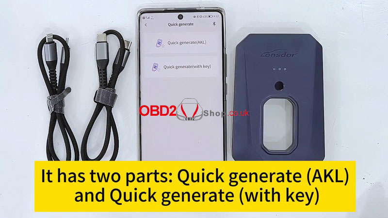 Tap "More function", and we can see all functions KW100 supported. Like getting version info, reading button function, modifying button type, detecting frequency sequence, modifying frequency, and unlocking key. These are also very important for a smart key. 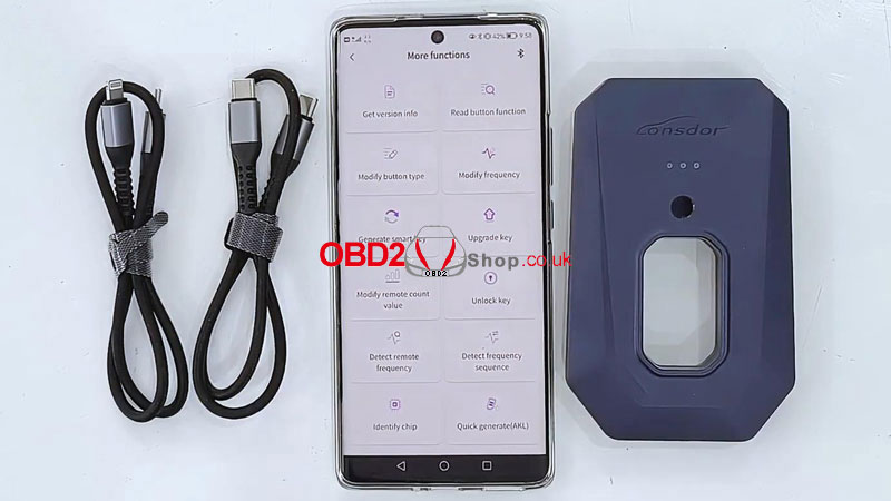 From the bottom of the APP, we can find Home, Upgrade, Service, and Mine. Home offers the functions of KW100. The upgrade is to update the device. Service is about after-sales. Mine includes your personal information. 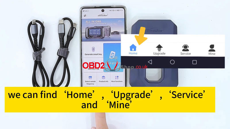 With KW100 + LT20 smart keys, users can get everything done in this small device. If users have any questions, they can leave messages on "Service". Tap "Online message" to leave your question, Lonsdor after-sales will answer you as soon as possible. Also, you can check your history message before reviewing the answer when you meet again. 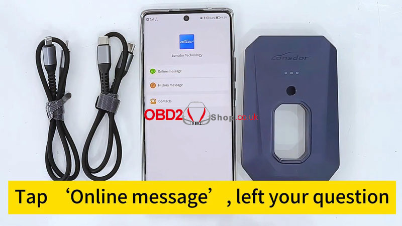
This post will guide you on how to install the MQB lock fastening (MQB-87) interface board from Yanhua ACDP Module 33.
Here comes the procedure: 1. Push the lock fastening of the interface board to the unlock position. Find the interface board installation area on the instrument according to the visual positioning mark on the interface board. 
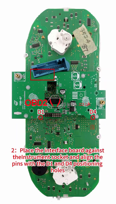
2. Place the interface board against the instrument socket and align the pins with the D1 and D4 positioning holes.
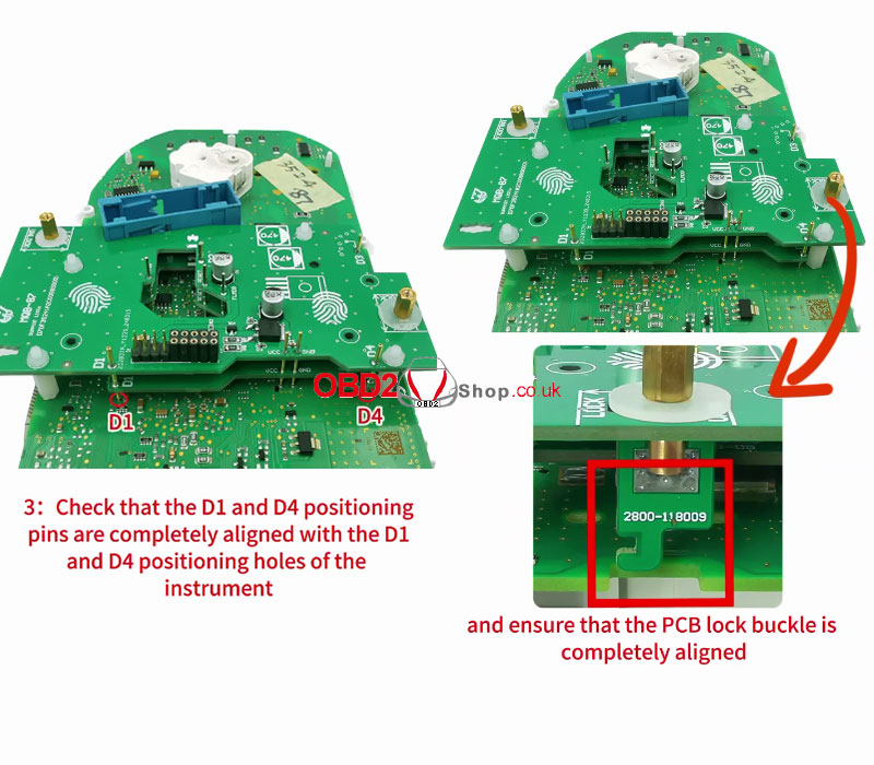
3. Check that the D1 and D4 positioning pins are completely aligned with the D1 and D4 positioning holes of the instrument and ensure that the PCB lock buckle is completely aligned.
4. Place your finger on the fingerprint position of the interface board press down on the interface board, and push the PCB lock buckle to the locked position to lock the interface board.
The installation is done. 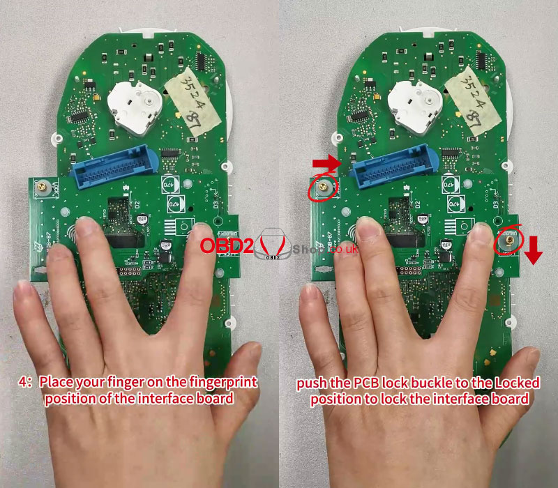
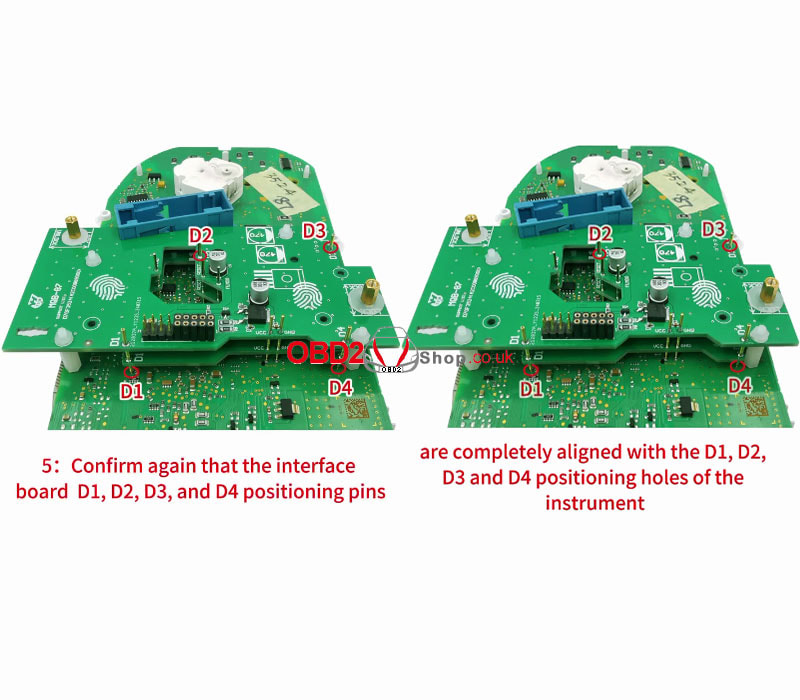
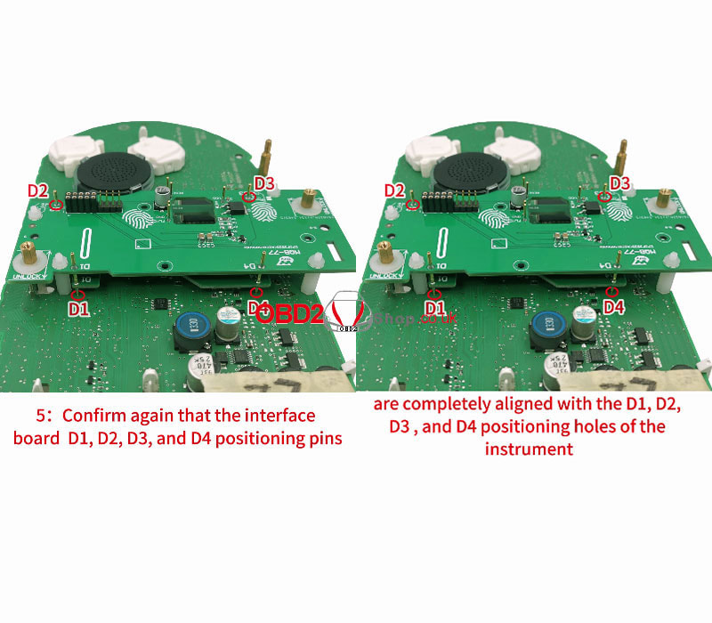
5. Confirm again that the interface board D1, D2, D3, and D4 positioning pins are completely alignined with the D1, D2, D3, and D4 positioning holes of the instrument.
Video Guide:
This post will guide you on how to install the MQB thumb screw-fastened (MQB-75) interface board from Yanhua ACDP Module 33.
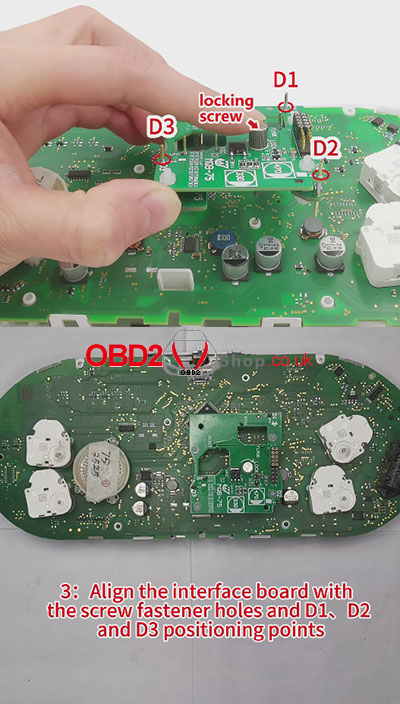
Here comes the procedure: 1. Find the interface board installation area on the instrument according to the visual positioning mark on the interface board. 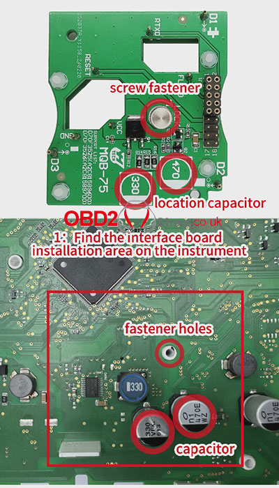
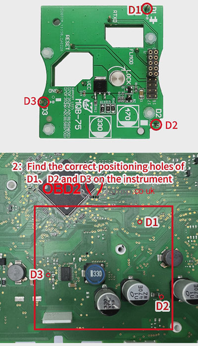
2. Find the correct positioning holes of D1, D2, and D3 on the instrument.
3. Align the interface board with the screw fastener holes and D1, D2, and D3 positioning points.
4. Press the interface board down with your left hand, tighten the locking screw with your right hand.
The installation is done. 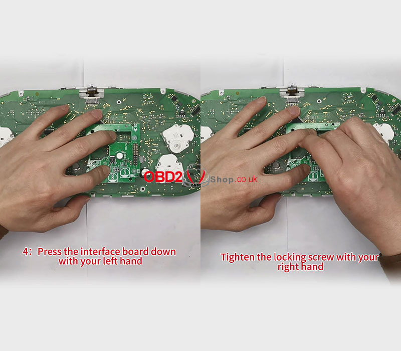
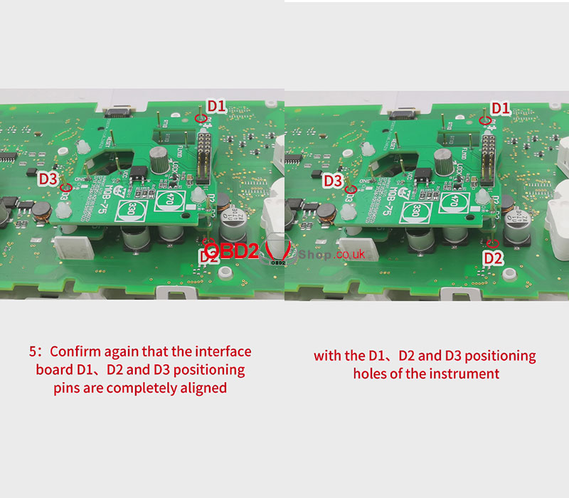
5. Confirm again that the interface board D1, D2 and D3 positioning pins are completely aligned with the D1, D2 and D3 positioning holes of the instrument.
Video guides:
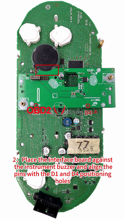
This post will guide you on how to install the MQB lock fastening (MQB-77) interface board from Yanhua ACDP Module 33.
Here comes the procedure: 1. Push the lock fastening of the interface board to the unlock position. Find the interface board installation area on the instrument according to the visual positioning mark on the interface board. 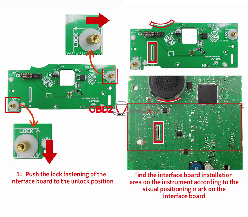
2. Place the interface board against the instrument buzzer and align the pins with the D1 and D4 positioning holes.
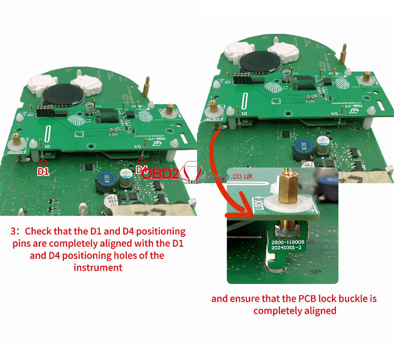
3. Check that the D1 and D4 positioning pins are completely aligned with the D1 and D4 positioning holes of the instrument and ensure that the PCB lock buckle is completely aligned.
4. Place your finger on the fingerprint position of the interface board
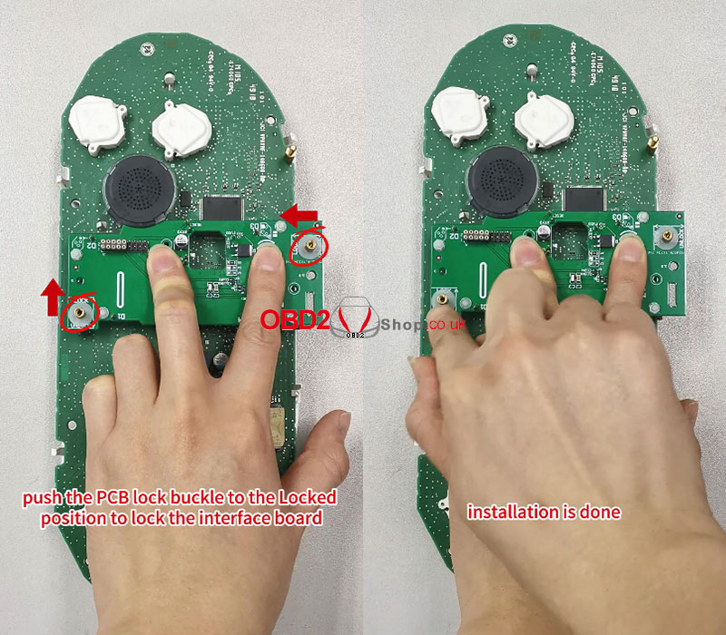
Press down on the interface board. Push the PCB lock buckle to the Locked position to lock the interface board. The installation is done. 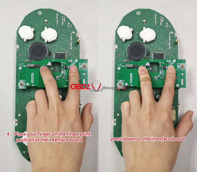
5. Confirm again that the interface board D1, D2, D3, and D4 positioning pins are completely aligned with the D1, D2, D3, and D4 positioning holes of the instrument.
Video guides:
This article will guide you on how to export data read by Yanhua ACDP. The steps for the Android system are as follows:
Open the ACDP App and update the ACDP software to version 3.0.118 or above. 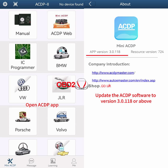
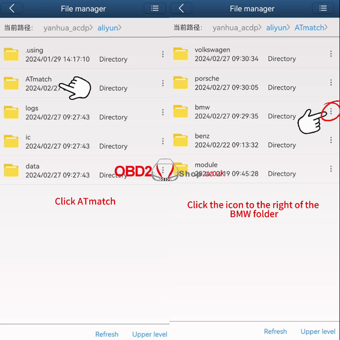
Click [Me]>>[My files], and click on the icon in the upper right corner.
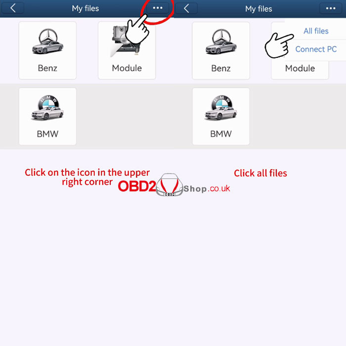
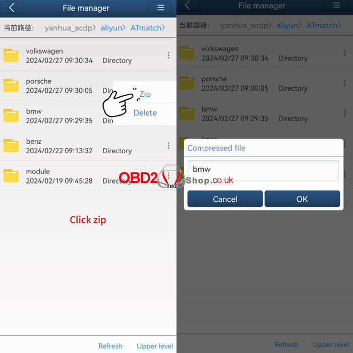
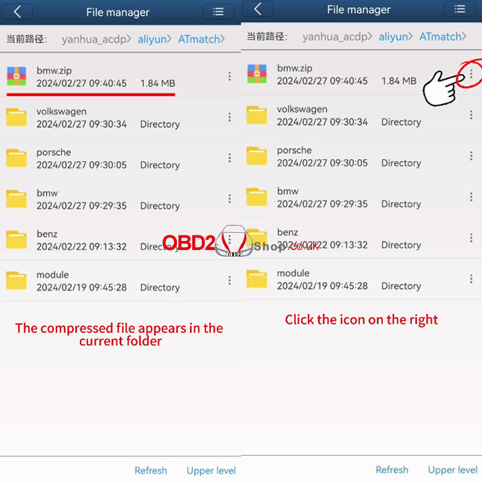
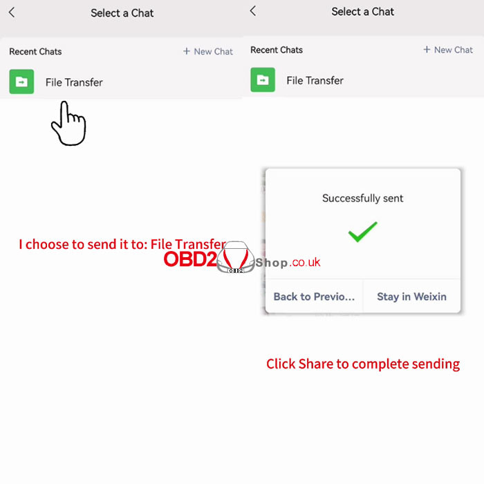
Click [All files]>>[ATmatch] Here we take exporting the BMW folder as an example. Click the icon to the right of the BMW folder, click [Zip], then click"OK" to continue. The compressed file appears in the current folder, click the icon on the right, then click [Share], and we use WeChat as an example, click "Share" to complete the sending. 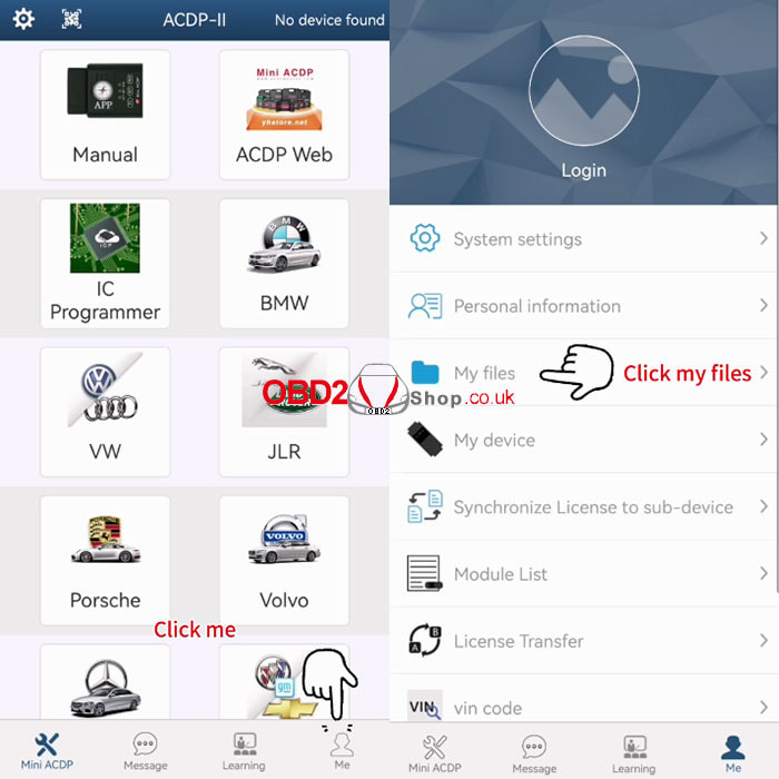
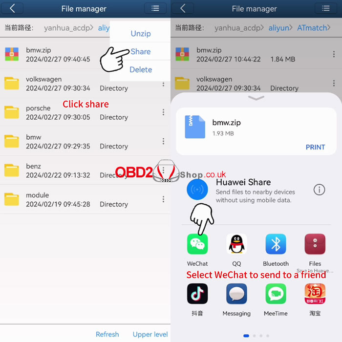
For more details please see the video:
This post will guide you on how to do the Benz 271 DME clone via Yanhua Mini ACDP and Module 18.
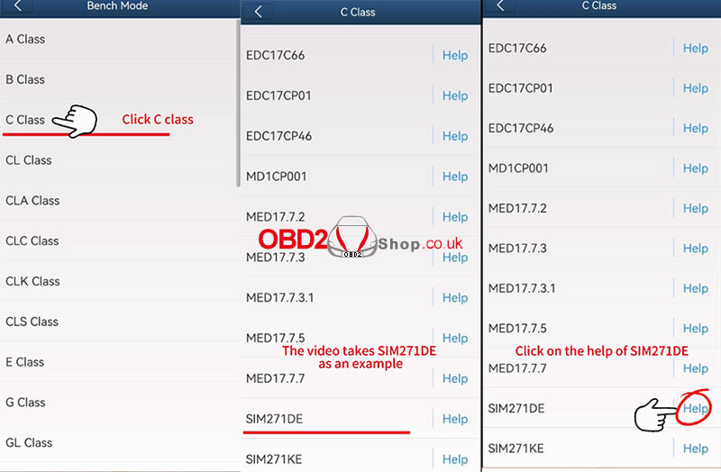
Power on the ACDP, open the ACDP app and confirm in the upper right corner that the ACDP device is connected. Click [Benz]>>[DME Clone]>>[Bench Mode]>>[C Class], then we click on the "Help" of SIM271DE. 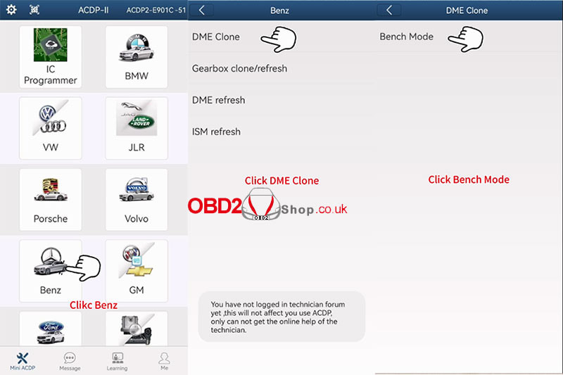
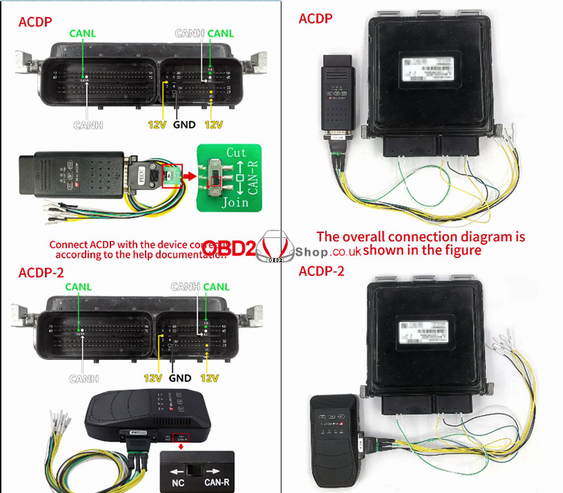
Connect ACDP with the device correctly according to the help documentation, the overall connection diagram is shown in the figure.
Then we click [SIM271DE] to do the DME clone.
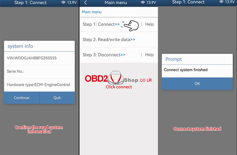
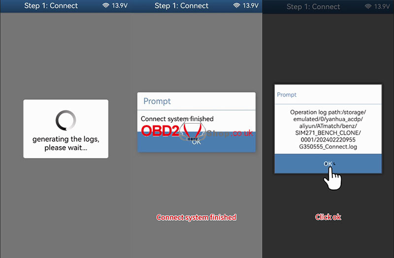
Step 1: Connect Click [Connect] Prompt: Please use the ACDP standard power adapter (voltage+ 12V, current>=2.5A). Click "OK" to continue. Prompt: Please connect ACDP with the DME, ensure a stable network connection, and DO NOT pull out the device while it working. Click "Continue". Confirm the read system information, and click"Continue". Confirm the system information and save a screenshot, click "OK" The connection system is finished. 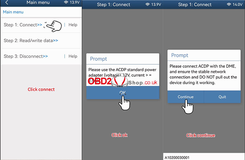
Step 2: Read/write data
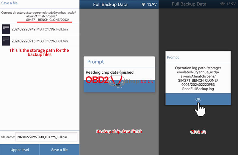
Click [Read/write data]>>[Full Backup Date] Prompt: Please use the ACDP standard power adapter (voltage+ 12V, current>=2.5A). Click "OK" to continue. Prompt: Please connect ACDP with the DME, ensure a stable network connection, and DO NOT pull out the device while it working. Click "Continue". Reading chip data, please wait... Prompt: Please save chip data Click "OK" to continue. This is the storage path for the backup files, confirm and click [Save a file]. Reading chip data finished. Click the icon on the top left corner to go back to the previous step. 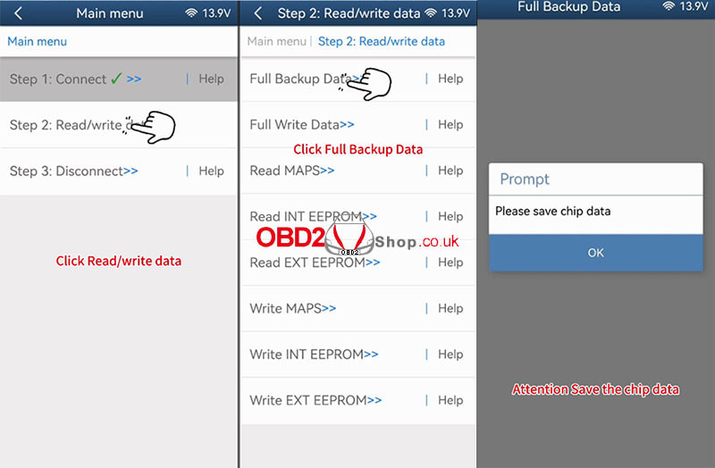
Step 3: Disconnect
Click [Disconnect] Prompt: Please use the ACDP standard power adapter (voltage+ 12V, current>=2.5A). Click "OK" to continue. Prompt: Please connect ACDP with the DME, ensure a stable network connection, and DO NOT pull out the device while it working. Click "Continue". Disconnect finished. 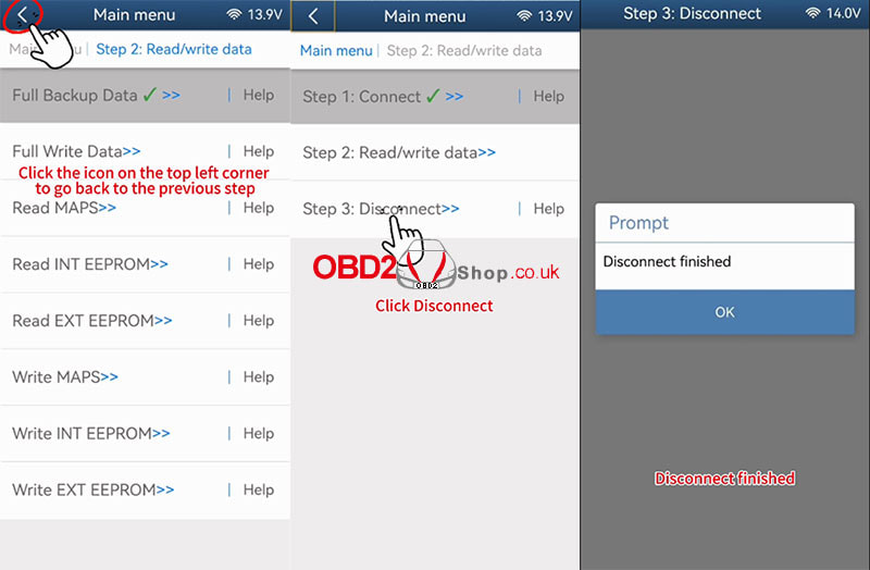
Connect another 271 DME, preparing to write the original files.
Step 1: Connect Click [Connect] Prompt: Please connect ACDP with the DME, ensure a stable network connection, and DO NOT pull out the device while it working. Click "Continue". Confirm the read system information, and click "Continue". Confirm the system information and save a screenshot, click "OK" to continue. The connection system is finished. 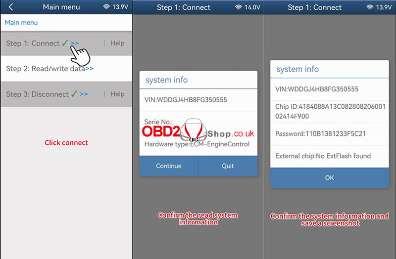
Step 2: Read/write data
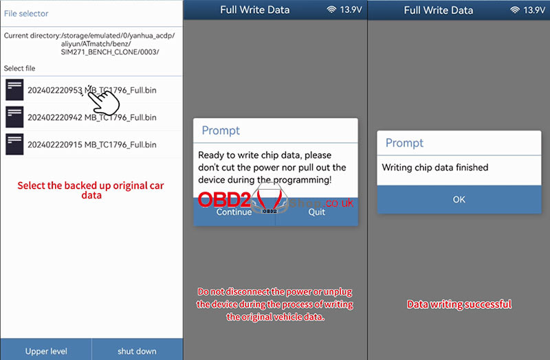
Click [Read/write data]>>[Full Write Data] Prompt: Please use the ACDP standard power adapter (voltage+ 12V, current>=2.5A). Click "OK" to continue. Prompt: Please connect ACDP with the DME, ensure a stable network connection, and DO NOT pull out the device while it working. Click "Continue". Prompt: Please select chip data. Click "OK" to continue. Select the backed-up original car data. Prompt: Ready to write chip data, please don't cut the power nor pull out the device during the programming! Click "Continue". Writing chip data, please wait... Writing chip data finished. Click the icon on the top left corner to go back to the previous step. 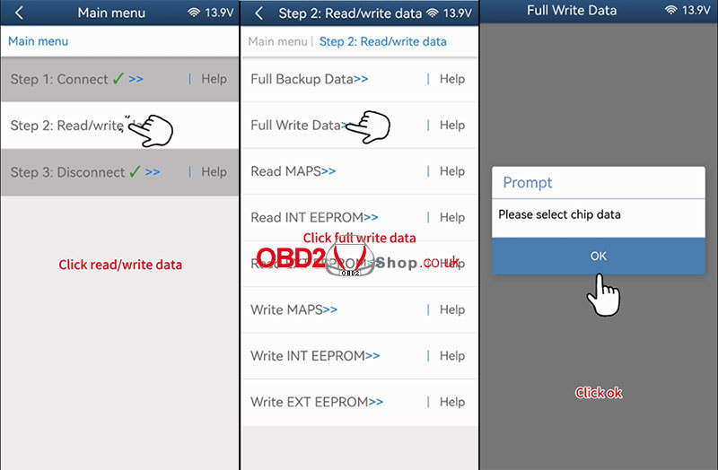
Step 3: Disconnect
Click [Disconnect] Click [Read/write data]>>[Full Write Data] Prompt: Please use the ACDP standard power adapter (voltage+ 12V, current>=2.5A). Click "OK" to continue. Prompt: Please connect ACDP with the DME, ensure a stable network connection, and DO NOT pull out the device while it working. Click "Continue". Disconnecting the system, please wait... Disconnect finished. 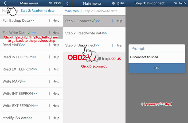
Video guides:
|
