|
How to clone Mercedes Benz VGS-NAG3 9GTronic gearbox with Yanhua Mini ACDP + Module 16? Follow this guide to learn how to do it. Note: click "Help" to check the connection diagram. Tools Required VGS-NAG3(9 Tronic) gearbox PTCU cable DB15-LAN adapter SH725XX interface board ACDP host Installation 1. Install the interface board. 2. Short circuit the CAN resistor on the DB15-LAN adapter to the "CAN-R" side. 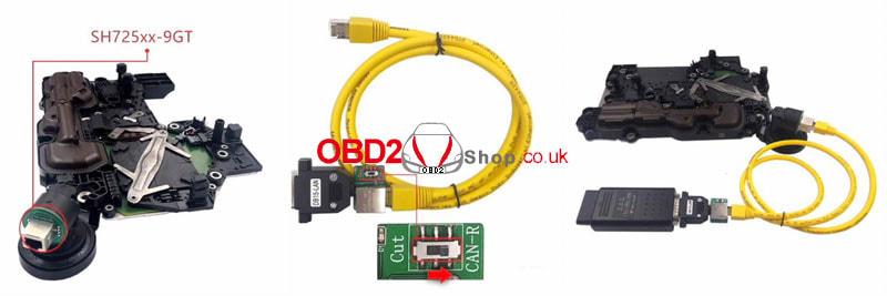 Operation Mini ACDP >> Benz >> Gearbox clone/refresh >> C class >> VGS-NAG3(9GTronic) >> Full backup data Connect ACDP with the gearbox. Remember the BOOT version & Bosch number. These 2 numbers of new gearbox should be same as original one. Save chip data file. 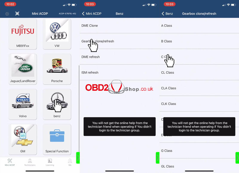 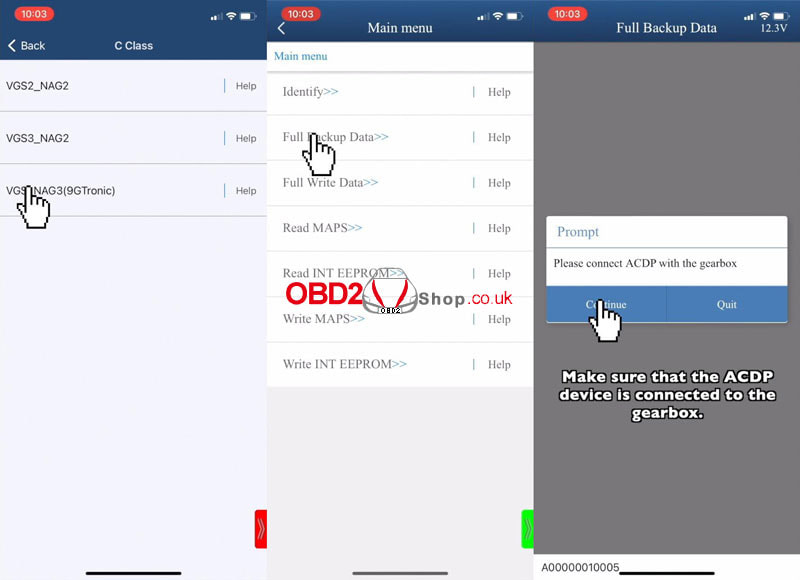 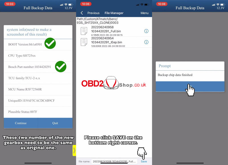 Connect the new VGS-NAG3(9Tronic) gearbox. Full write data >> Continue >> Check BOOT version & Bosch number, continue. Select chip data file to write. Write data finished. Completed! 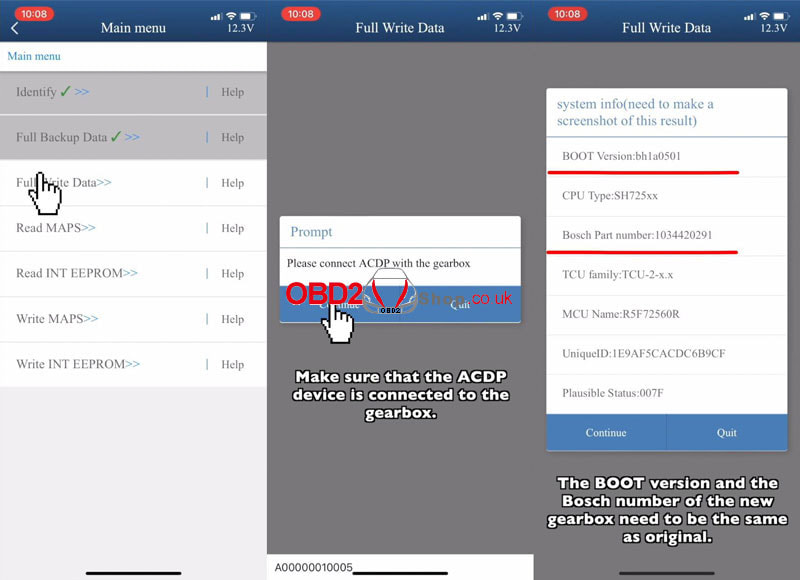 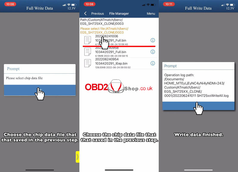
0 Comments
This article lists some problems and solutions that may occur while using the PCMTuner ECU programmer. Problem 1: Go to the official PCMTuner website and get a 419 error. 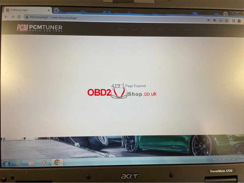 Solution: Use the Firefox browser instead of Google. Problem 2: The error shown in the figure below appears when opening the PCMTuner software. 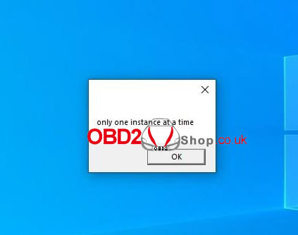 Solution: This is caused by opening more software, restarting or ending pcmtuner in the task manager. Problem 3: Win7 system prompts the specified file not found error. 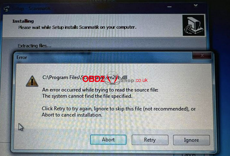 Solution: Download and install framework 4.8. Run setup as admin, disable all antivirus and real-time scans.
For more information on PCMtuner, please pay attention to http://blog.obd2shop.co.uk/
Yanhua Mini ACDP with Module 22 can support GM 6TXX / 6LXX gearbox clone, this article will take GM 6L50 as an example to guide you on how to do it.
The accessories we need: 20 PIN Cable OBP+ICP Adapter ACDP Host 6LXX Interface Board 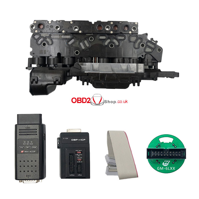
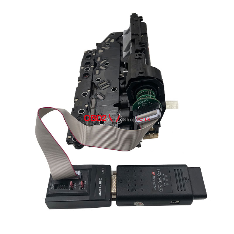
Connect the ACDP, OBP + ICP adapter, interface board and gearbox as the picture shows.
Open the Mini ACDP APP, choose "GM" → "Gearbox clone" → "GM 6L50"
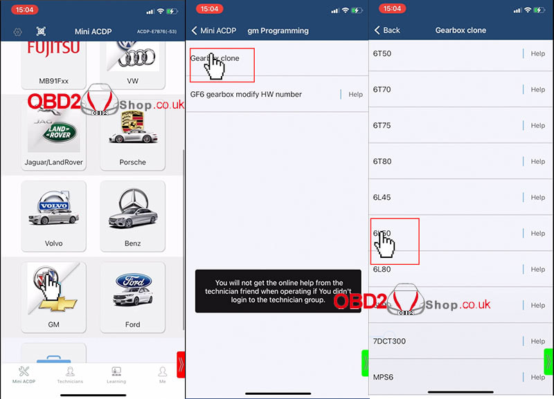
Backup chip data
Choose "Full backup data", and make sure the gearbox is connected with ACDP. Confirm the system information and save the screenshot, click continue. After the clip data has been read successfully, click "Save" in the lower right corner. 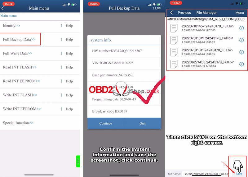
Write chip data
Choose "Full Write data", and make sure the gearbox is connected with ACDP. Confirm the system information and save the screenshot, click continue. Select the original data file that saved in the previous step. 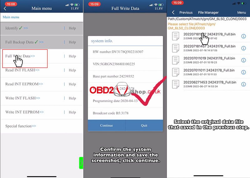
The device is about to write clip data, please make sure these two gearbox computers' model are the same.
Writing chip data finished. 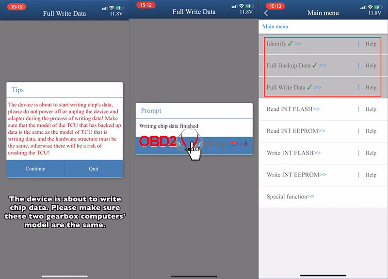
For more detailed steps, please refer to the video:
Yanhua FEM/BDC Special Programming Clip is designed to pre-process BMW FEM/BDC module without having to remove or solder 95128/95256 chip. With it, you don't need to worry about how thick the paint on the chip! Highlights 1. Fast clamping 2. Safe & reliable 3. Simple positioning, not easy to slip. 4. Easy to solve the problem of chip paint thick & puncture socket slip off. 5. Compatible with Yanhua Mini ACDP, CGDI, VVDI, Autel, Launch X431. How to install FEM/BDC Special Programming Clip? 1. Insert the 2 screws of the special programming clip into PCB plate holes. 2. Lock the PCB lock. 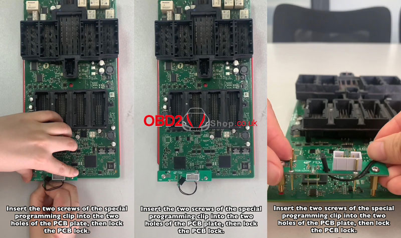 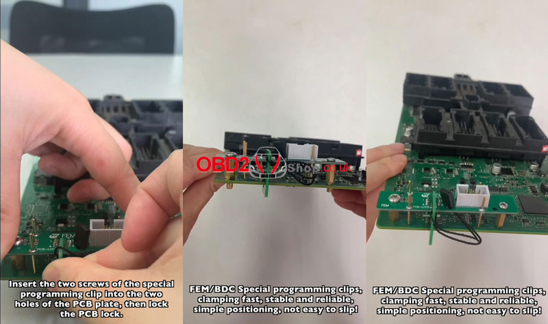 FEM connection diagram 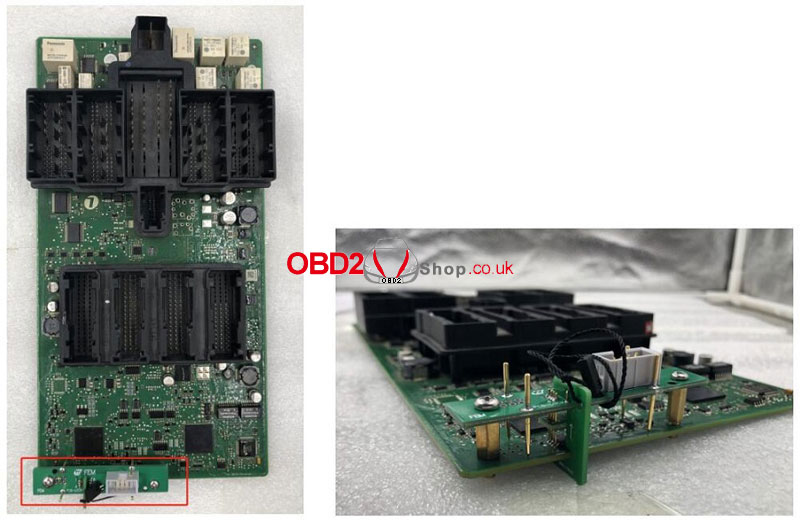 BDC connection diagram 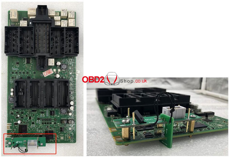 Problem: I've got the Lonsdor K518ISE Key Programmer recently, but failed to bind LKE Smart Key Emulator to K518 for several times. It says:" Please place key emulator into this device's card slot." or "Failed to obtain data, please make sure the key emulator is placed correctly in this device's card slot." 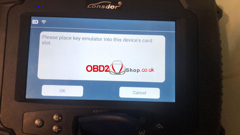 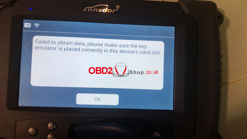 How to solve, any ideas? Solution 1. Make sure the battery is installed. 2. Try different positions with few more times, noticed the coil head should place down in Lonsdor K518 key slot. Can also open key shell.  3. Check LKE key version: Special functions >> Simulated chip >> Obtain LKE data 4. Update LKE key if it was BOOT version: Special functions >> Simulated chip >> Generate simulated chip >> 4D type >> Blank 4D simulated chip 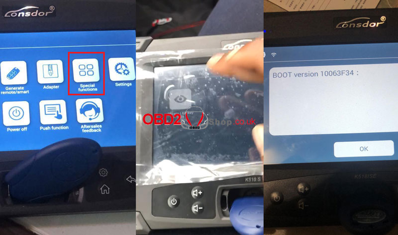 Feedback
Thanks to Obd2shop engineer, problem was solved! LKE smart key can be normally used. Read also How to Bind LKE Smart Key Emulator to Lonsdor K518ISE? Technical support www.obd2shop.co.uk Godiag GT107 Gearbox Data Adapter is designed to clone, diagnose and repair DSG gearbox ECU for maintenance engineers. Supports gearbox ECU DQ250, DQ200, VL381, VL300, DQ500, DL501. Perfectly compatible with PCMTuner, KESS V2, PCMFlash, KTMBench, etc. 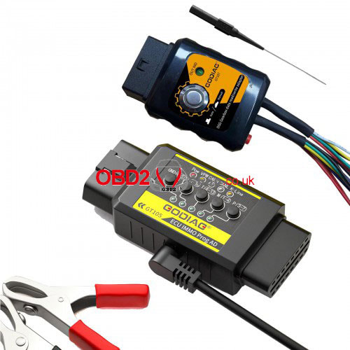 Features Read, write, and adjust DSG gearbox data. Support PCMflash module 58 all DSG models. Easy operation, 2 selection modes for PCMFlash(auto/manual), manual mode for other ECU diagnostic software. Indicators can show communication status during working. Support car battery power supply. Attached: Godiag DSG GT107 PIN OUT DQ200(0AM, 0CW), DQ250(02E,0D9), VL381(0AW), DQ500(0BT, 0BH) 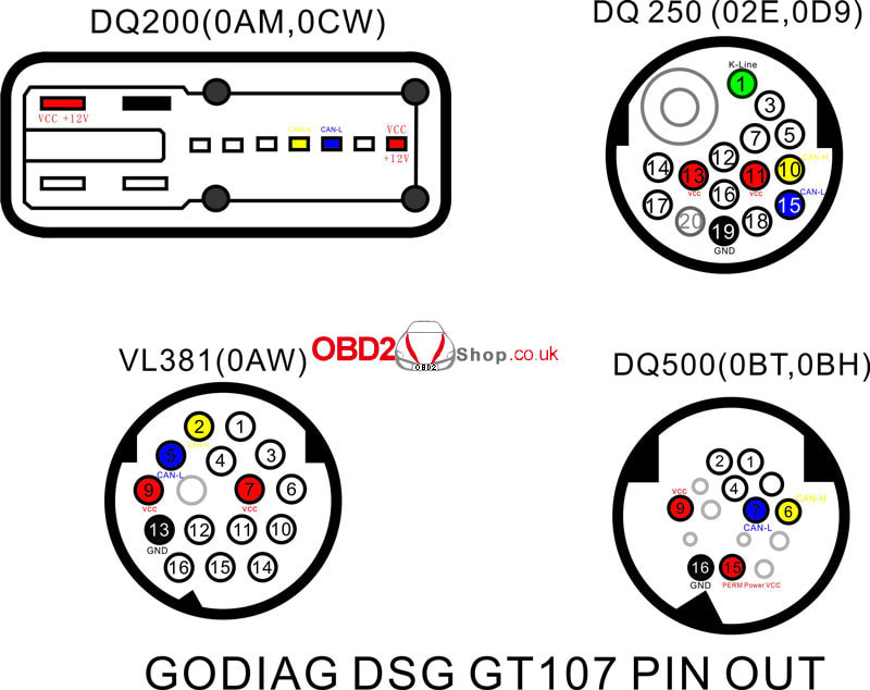 V30(01J), VL300(01J) 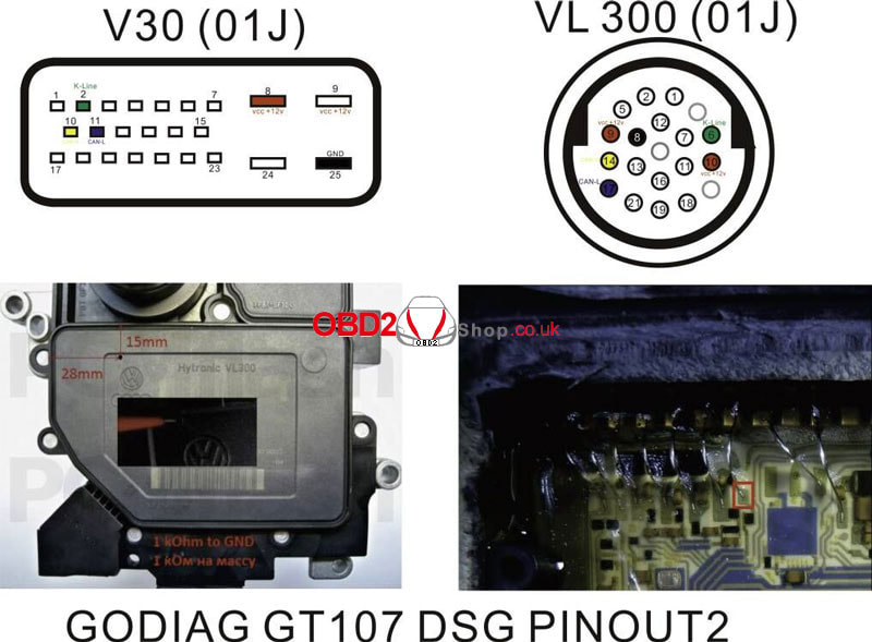 DL382(0CK), DL501(0B5), Renault DC0/DC4 Gen2, Honda LuK-UDCT 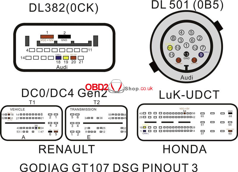 PCMTuner + GT107 clone gearbox connection diagram 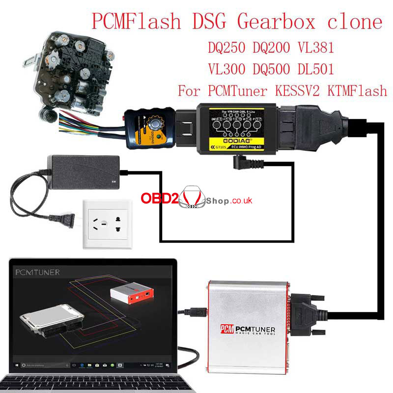 KESS V2 + GT107 clone gearbox connection diagram 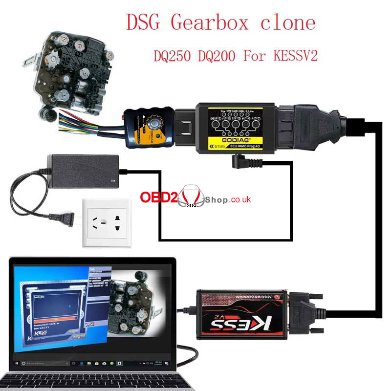 GT107 clone gearbox on car connection diagram 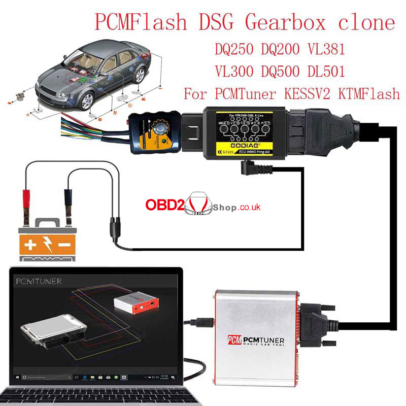 Godiag GT107 + PCMTuner read DQ250(02E) ECU 1. Connect GT107, gearbox & PCMTuner; 2. Press ignition button to switch manual mode for diagnosis: (GT105 red & blue lights are continuous flashing) [58] VAG: DQ250C(02E)K-Line/ >> Identification 3. Press GT107 button to switch auto mode for data reading: (GT105 red & blue lights are on but stop flashing) [59] DQ250E/FMQB Boot(MICRO) >> Identification >> Read (* When GT107 green light is on, it's "Auto", otherwise it's "Manual".) 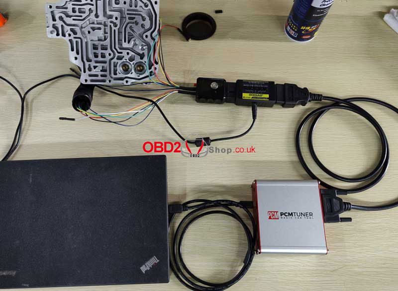 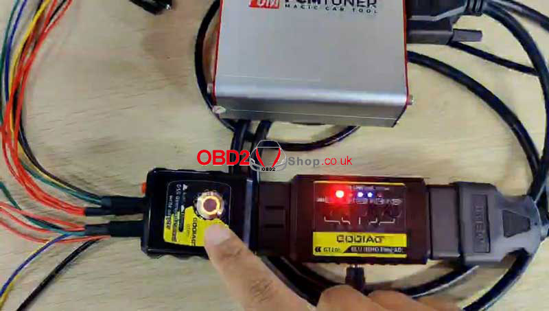 Godiag GT107 + PCMTuner chip tuning DQ200 ECU Select ECU: [58] VAG: DQ200/MQB Boot(MICRO) (*PCMTuner supports 120Ω power supply, no need to press red button for short-circuit. For KESS will need.) 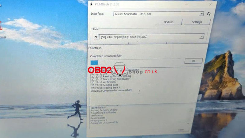 Godiag GT107 + KESS V2 read DQ200 ECU 1. Connect GT107, gearbox & KESS according to diagram; 2. Press 120Ω red button & ignition button for manual mode; 3. Open KESS software: Temic DQ200 >> Read >> ID/Reading 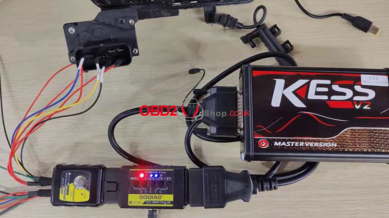 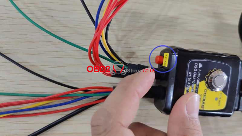 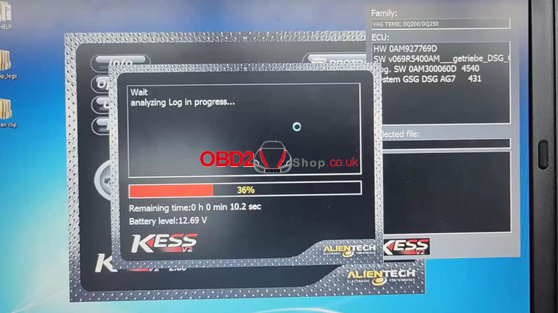 Godiag GT107 + KESS V2 read DQ250 ECU ECU model: DQ250(02E) KESS path: Temic DQ250 >> OK >> ID/Reading 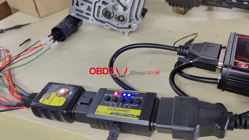 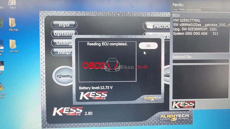 VOCOM II Mini is a wireless device that supports to the diagnosis of Volvo heavy-duty truck via WiFi. Small and portable, with no need for wires. This is an initial guide on WiFi settings & firmware upgrades. How to setup Volvo VOCOM 2 WiFi? 1. Power on the Mini Vocom2 dongle and the lights will be flashing. Find the WIFI signal Vocom2D_******* from laptop. Click "Connect". 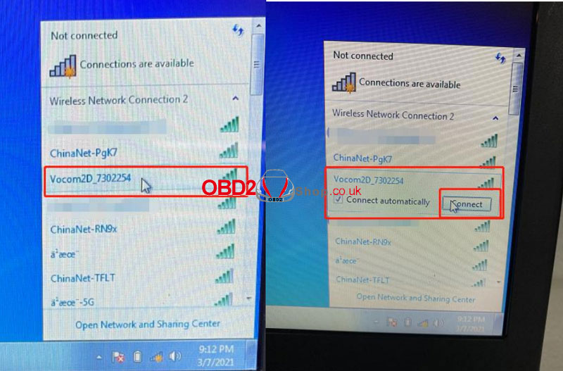 2. Input “v2d+ SN num”, SN number is 7 digits which you can find it from the backside of the VOCOM2 dongle. Then click "OK" and done. 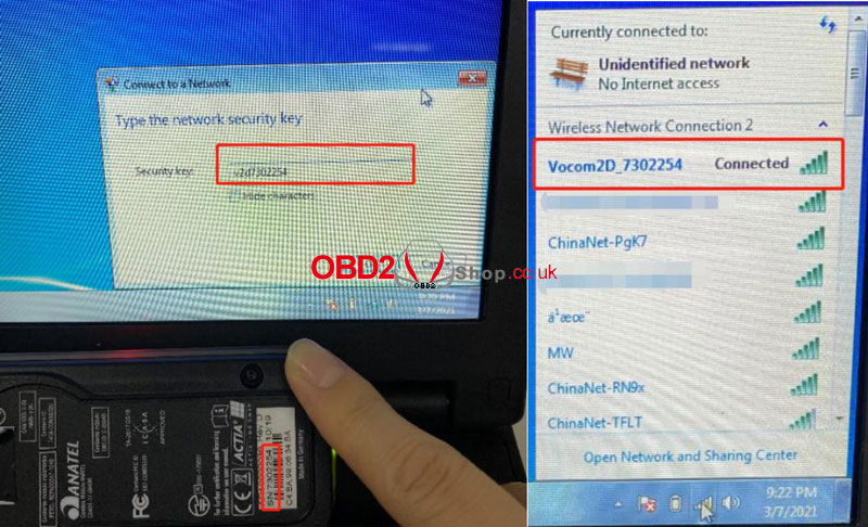 How to update Volvo VOCOM 2 firmware? Note: Make sure the Mini Vocom2 is powered up by 24V ECU or truck. Low voltage will affect the upgrade process. Follow the path: All Programs >> VOCOM II >> VOCOMII Configurator >> Setting >> Advanced >> Update device firmware >> Update button 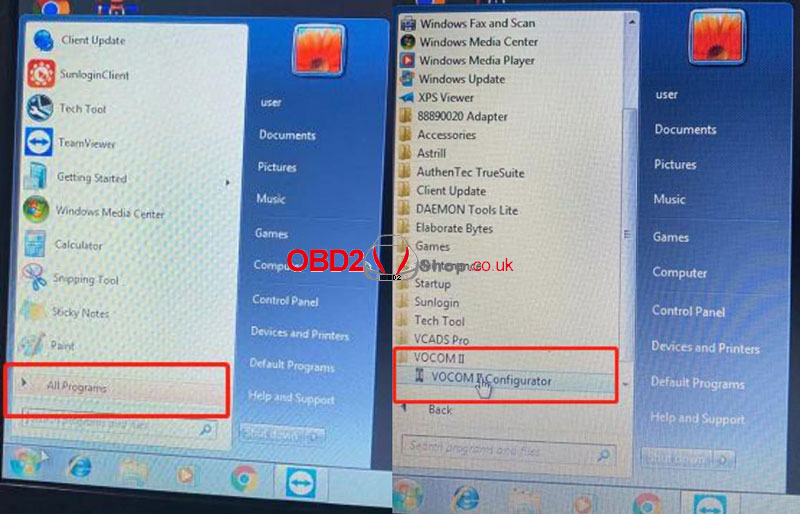 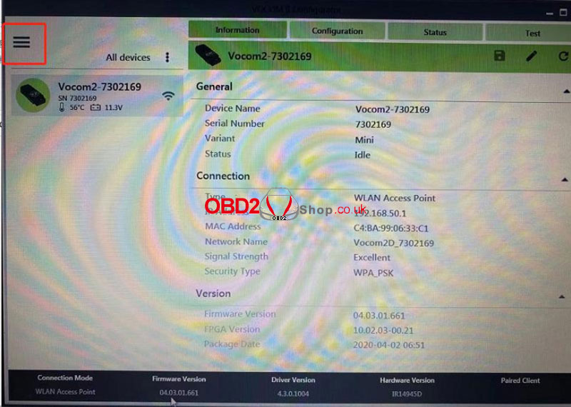  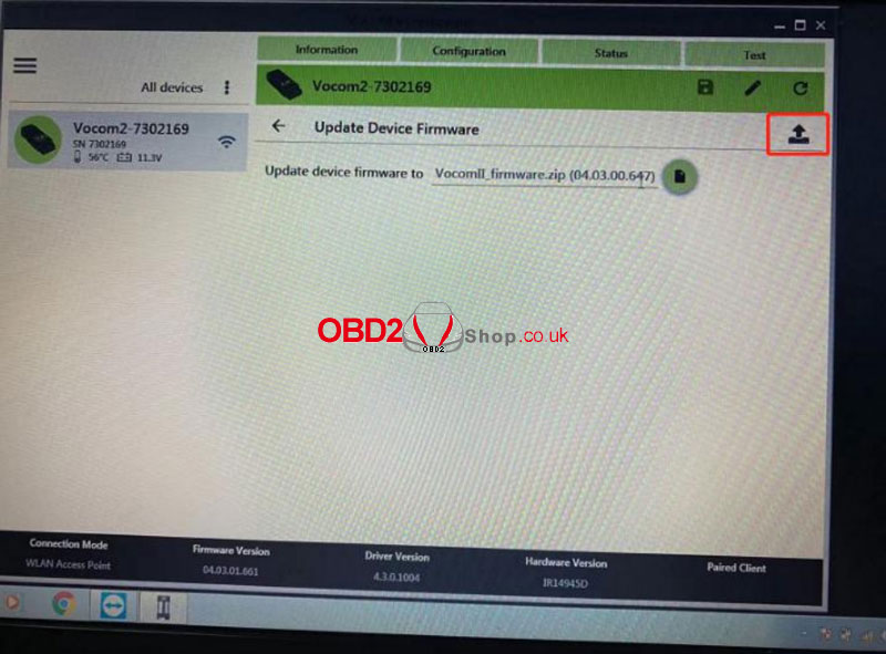 It'll run the TECH TOOL automatically when the firmware update is finished... 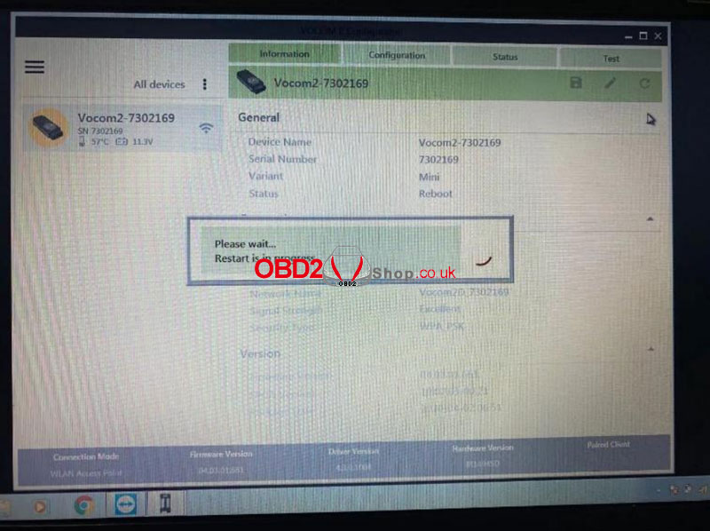 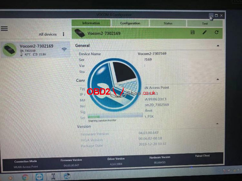 Log in then it's done. 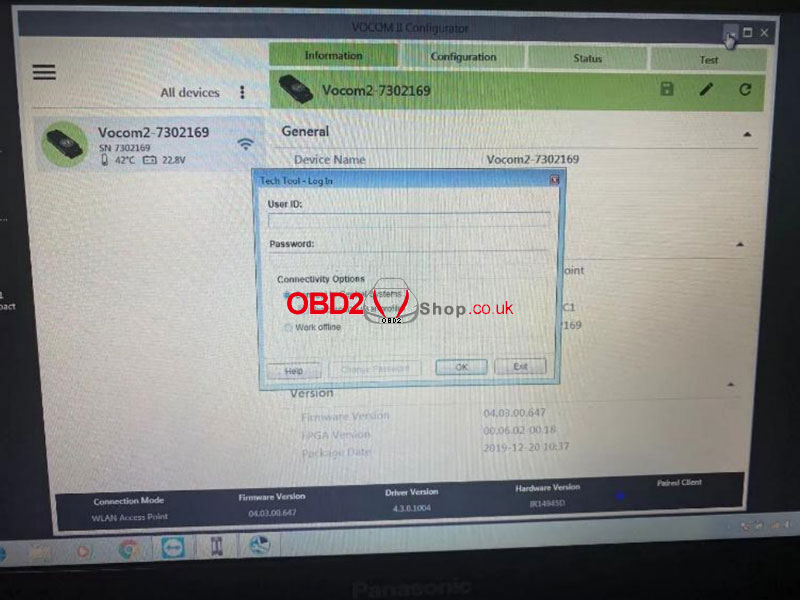 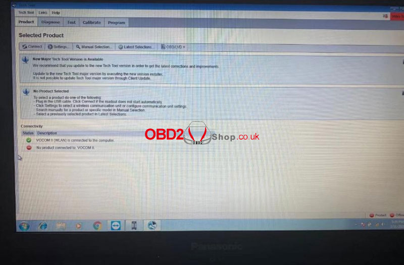 This quick start guide covers the wifi setting, registration, and updating of Autel MaxiSYS MS906 Pro-TS Bi-Directional Diagnostic and TPMS Service Tablet. Part 1. Autel MaxiSYS MS906 Pro-TS Wifi Setting Once you fire up your tool, the first step should be to connect to a wifi network which you can find in settings, system settings, then wifi, toggle on the wifi and allow the device to compile a list of available networks. Choose your network, then enter your credentials to join the network. 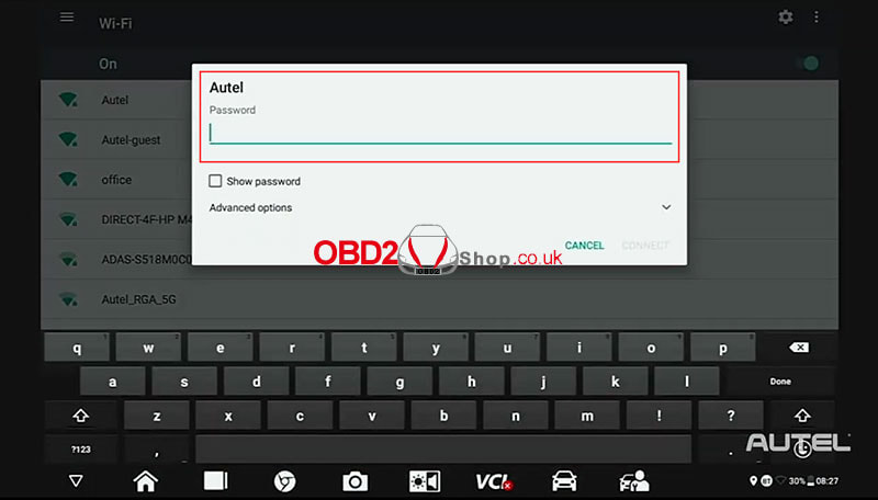 Part 2. Autel MaxiSYS MS906 Pro-TS Registration Once you are on wifi you will need to register your new tool this can be done quickly and easily right on your tablet or at pro.autel.com. If you already have an Autel account just sign in with your account id and password. 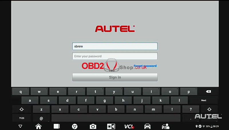 For first-time Autel buyers click on the create Autel id button on the bottom. 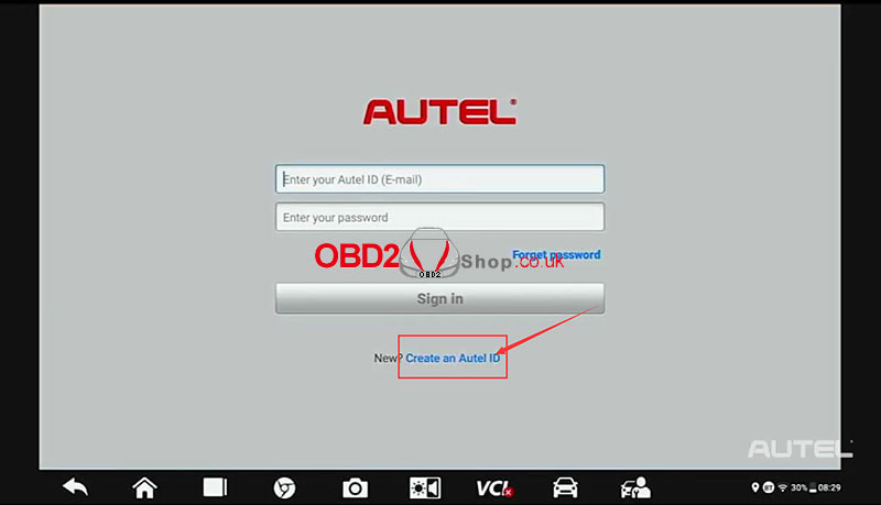 Enter your email address, then click acquire verification code, check your email for the code. 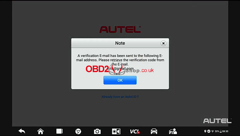 Once you have the code, enter your password. Please note your password must consist of seven numbers and at least one letter. Next enter your verification code and click sign up. 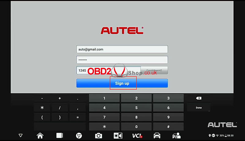 Once you have confirmation click register to register the tool. Your serial number and password will self-fill click register, and now you get a confirmation that you have successfully registered your tool. 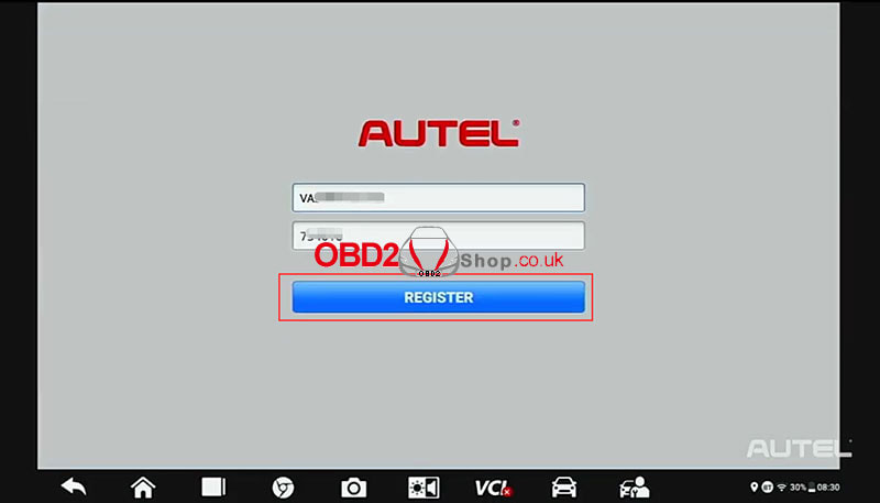 Part 3. Autel MaxiSYS MS906 Pro-TS Updating This is perhaps the most important step you need to ensure your software is up to date. Click update starts at the top and installs any system updates that are available, next proceed to any brands that you routinely service in your shop. 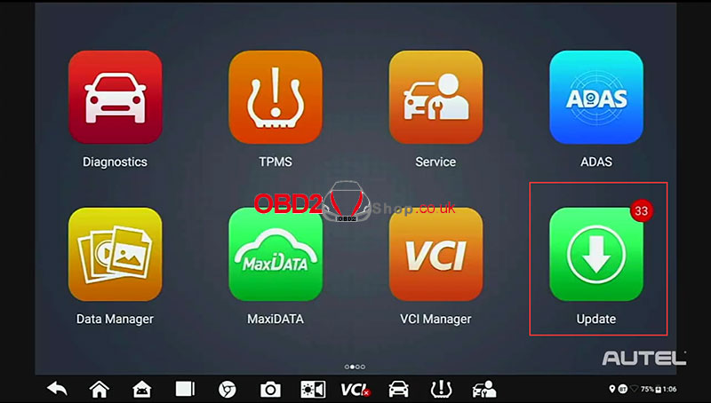 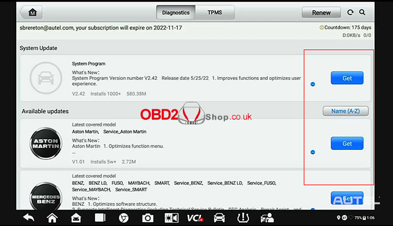 Once you're done select TPMS at the top and check for any TPMS updates that may be available. 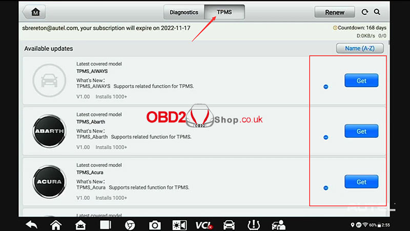 After you complete these updates, power up and connect to your VCI to check for available updates. If there's an update available install the update please note that do not leave the screen until the VCI update is finished installing. 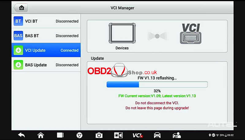 For more information on Autel MaxiSYS MS906 Pro-TS please follow https://www.obd2shop.co.uk/
Here Obd2shop.co.uk provides the latest 2022 free download link for Orange 5 Super Pro V1.35 full function & V1.36 software. Safe and virus-free, 100% tested! Where to free download Orange 5 Super Pro: https://mega.nz/file/6c4nBQJb#StikKVtqZ0ucFEP1WqDkCOlKeI5PwbD7ZslH70rt3ZQ Size: 1.88G (Super Pro: 2G, V1.36 software: 60MB) Orange 5 V1.36 Version: https://mega.nz/file/eYxhlBKC#ItU2jSjrpBTVZShJU_CIaU0Gvid8tWK4lV25m9Pdang Size: 214MB Operation Instruction 1. Before installing Orange 5 Super Pro software, please connect the device to the computer. 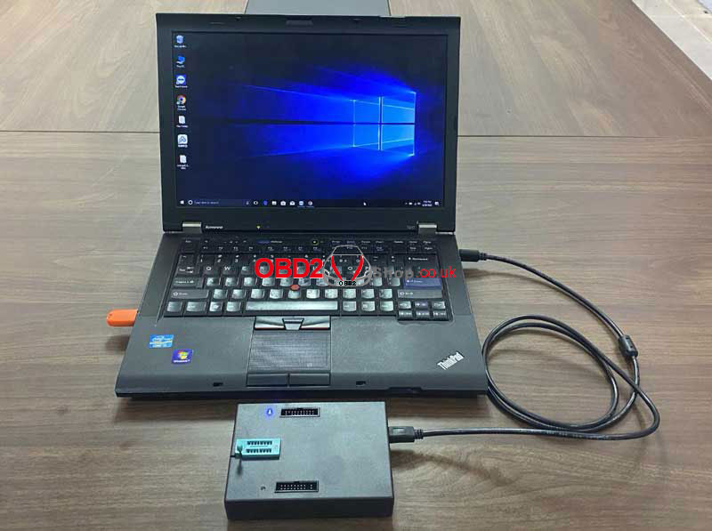 2. When the "USB device not found" pop-up window appears, the device driver is not installed. 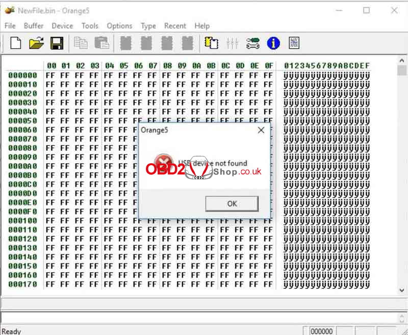 3. Computer Management >> Device Manager >> Ports(COM&LPT) >> USB Serial Device(COM5) >> Update driver >> Browse my computer for driver software >> Browse >> orange5_SUPER PRO >> Driver >> x32/x64 >> Next Once the "ORANGE5 USB" is coming out, which means successful. 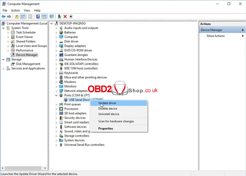 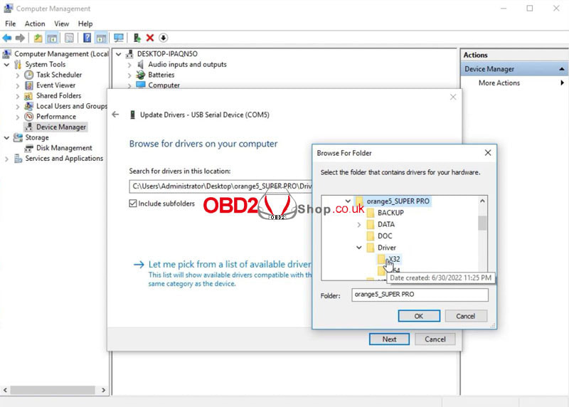 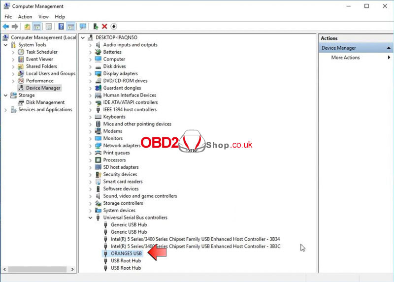 4. Before opening Orange 5 Super Pro V1.35 software, please connect the chip to be tested. 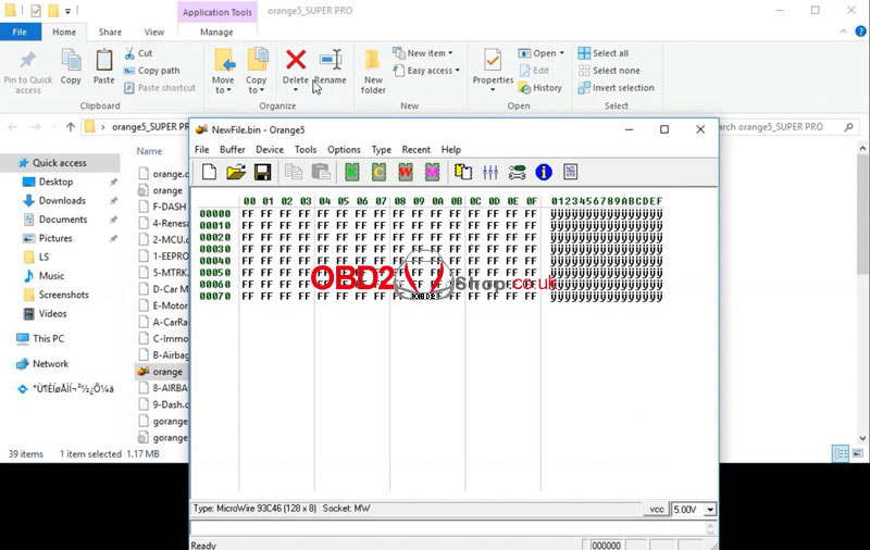 5. Orange 5 has 2 languages: English & Russian(Options >> Language) 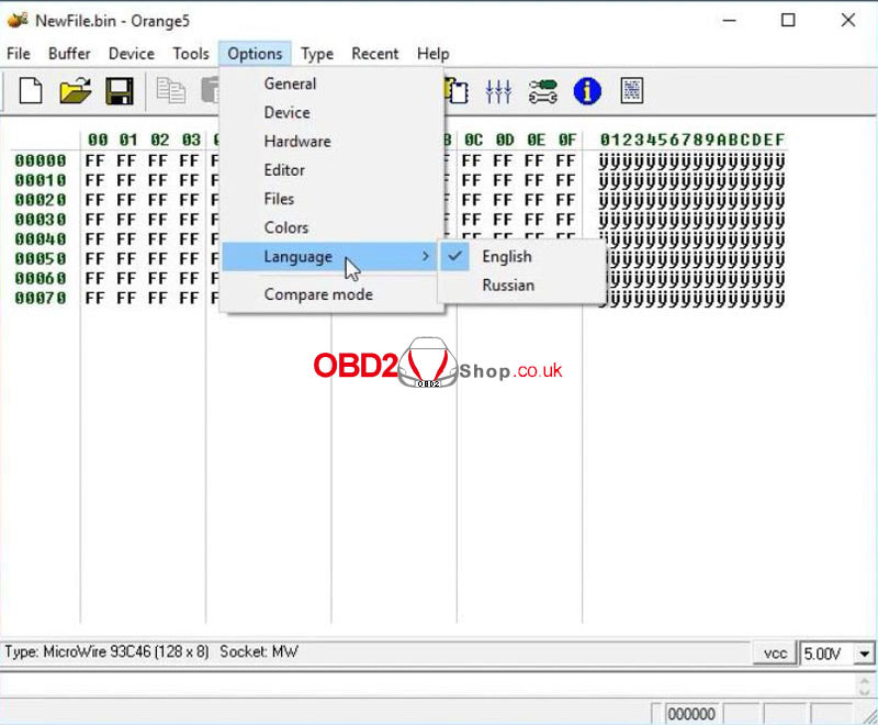 This article solves the problems related to updating the PCMtuner ECU programmer software. Part 1. How to upgrade the software The software is divided into 2 parts 1) PCMtuner online upgrade When there is a new version prompt, just click "OK" to upgrade. 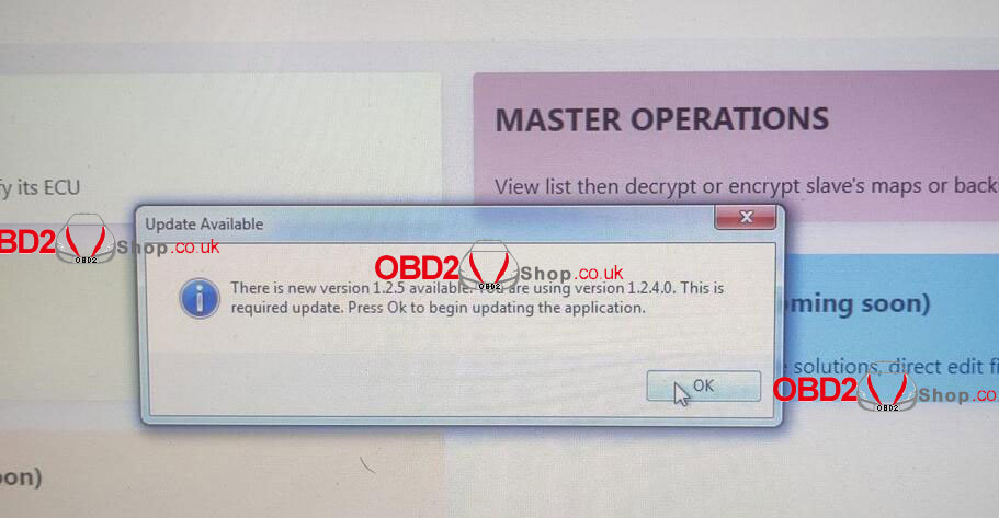 2) PCMflash cannot be upgraded online Subsequent upgrades i.e MG2 MD1 etc, are realized by new adapters. 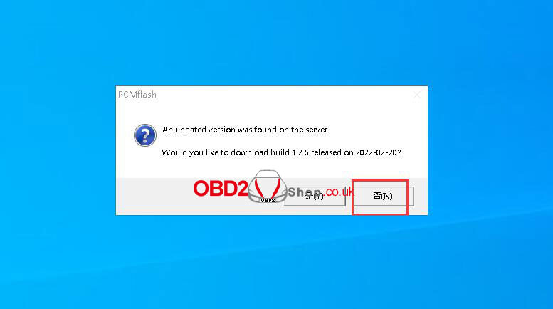 Part 2. Errors caused by software upgrades Problem: USB Dongle Not Accessible error caused by upgrading PCMflash software. 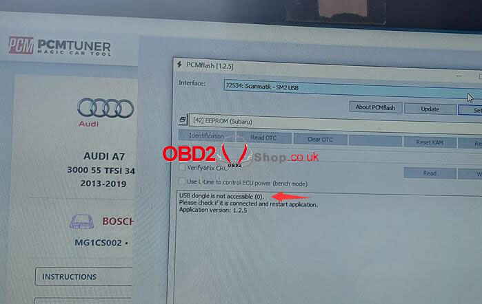 Uninstall pcmflash1.2.5 and reinstall the app 1.20 software (make sure to disable the antivirus software)
pcmflash 1.20 installation package: https://mega.nz/file/Gr5i1KAJ#HV2rPWP7T2cmGFr7EJM2-LZilNGGUDeI7QXRqQbf1gI For more technical services of PCMtuner, please continue to pay attention to http://blog.obd2shop.co.uk/ |
